Infiniti G35 (V35) Sedan. Manual - part 1414


  Index      Infiniti     Infiniti G35 (V35) Sedan - service repair manual 2007 year


Search            


Content   ..  1412  1413  1414  1415   ..


Infiniti G35 (V35) Sedan. Manual - part 1414


TM-348

< DISASSEMBLY AND ASSEMBLY >

[5AT: RE5R05A]

MID SUN GEAR, REAR SUN GEAR, HIGH AND LOW REVERSE CLUTCH HUB

9.

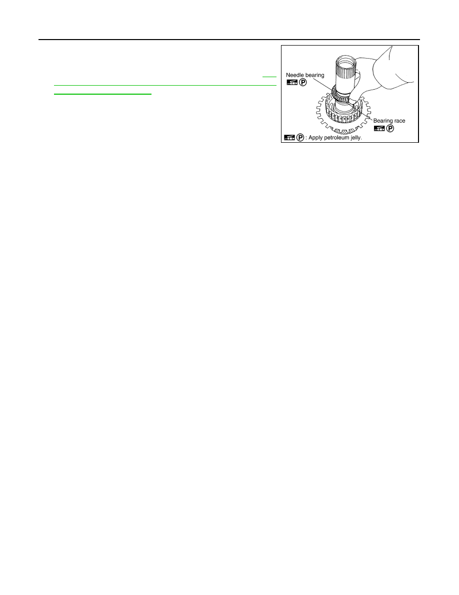
Install needle bearing and bearing race to high and low reverse
clutch hub.

CAUTION:

Take care with the direction of needle bearing. Refer to 

TM-

289, "Location of Adjusting Shims, Needle Bearings, Thrust
Washers and Snap Rings"

.

Inspection

INFOID:0000000000957206

• High and Low Reverse Clutch Hub Snap Ring, Rear Sun Gear Snap Ring

Check for deformation, fatigue or damage.

CAUTION:

If necessary, replace the snap ring.

• 1st One-way Clutch

Check frictional surface for wear or damage.

CAUTION:

If necessary, replace the 1st one-way clutch.

• Mid Sun Gear

Check for deformation, fatigue or damage.

CAUTION:

If necessary, replace the mid sun gear.

• Rear Sun Gear

Check for deformation, fatigue or damage.

CAUTION:

If necessary, replace the rear sun gear.

• High and Low Reverse Clutch Hub

Check for deformation, fatigue or damage.

CAUTION:

If necessary, replace the high and low reverse clutch hub.

SCIA2854E

HIGH AND LOW REVERSE CLUTCH

TM-349

< DISASSEMBLY AND ASSEMBLY >

[5AT: RE5R05A]

C

E

F

G

H

I

J

K

L

M

A

B

TM

N

O

P

HIGH AND LOW REVERSE CLUTCH

Exploded View

INFOID:0000000000957207

Disassembly

INFOID:0000000000957208

1.

Remove bearing race from high and low reverse clutch drum.

2.

Using a flat-bladed screwdriver, remove snap ring from high and
low reverse clutch drum.

3.

Remove drive plates, driven plates and retaining plate from high
and low reverse clutch drum.

Assembly

INFOID:0000000000957209

1.

Install drive plates, driven plates and retaining plate in high and low reverse clutch drum.

CAUTION:

1.

High and low reverse clutch drum

2.

Driven plate

3.

Retaining plate

4.

Snap ring

5.

Drive plate

6.

Bearing race

SCIA5239E

SCIA5215E

SCIA2868E

TM-350

< DISASSEMBLY AND ASSEMBLY >

[5AT: RE5R05A]

HIGH AND LOW REVERSE CLUTCH

Take care with the order of plates.

2.

Using a flat-bladed screwdriver, install snap ring in high and low
reverse clutch drum.

3.

Install bearing race to high and low reverse clutch drum.

CAUTION:

Take care with the direction of needle bearing. Refer to 

TM-

289, "Location of Adjusting Shims, Needle Bearings, Thrust
Washers and Snap Rings"

.

Inspection

INFOID:0000000000957210

Check the following, and replace tranmission assembly if necessary.
• High and Low Reverse Clutch Snap Ring

Check for deformation, fatigue or damage.

• High and Low Reverse Clutch Drive Plates

Check facing for burns, cracks or damage.

• High and Low Reverse Clutch Retaining Plate and Driven Plates

Check facing for burns, cracks or damage.

1

:  Snap  ring

2

: Retaining plate

3

: Drive plate

4

: Driven plate

Drive plate / 
Driven plate

: 4/4

SCIA6735E

SCIA2868E

SCIA5215E

DIRECT CLUTCH

TM-351

< DISASSEMBLY AND ASSEMBLY >

[5AT: RE5R05A]

C

E

F

G

H

I

J

K

L

M

A

B

TM

N

O

P

DIRECT CLUTCH

Exploded View

INFOID:0000000000957211

Disassembly

INFOID:0000000000957212

1.

Using a flat-bladed screwdriver, remove snap ring from direct
clutch drum.

2.

Remove drive plates, driven plates, dish plate and retaining
plates from direct clutch drum.

Assembly

INFOID:0000000000957213

1.

Install drive plates, driven plates, dish plate and retaining plates in direct clutch drum.

CAUTION:

Take care with the order of plates.

1.

Direct clutch drum

2.

Dish plate

3.

Retaining plate

4.

Driven plate

5.

Retaining plate

6.

Snap ring

7.

Drive plate

SCIA7015E

SCIA2868E

1

:  Snap  ring

2

: Retaining plate

3

: Drive plate

4

: Driven plate

5

: Dish plate

Drive plate / 
Driven plate

: 5/4

SCIA6952E


Content   ..  1412  1413  1414  1415   ..