Infiniti G35 (V35) Sedan. Manual - part 1348


  Index      Infiniti     Infiniti G35 (V35) Sedan - service repair manual 2007 year


Search            


Content   ..  1346  1347  1348  1349   ..


Infiniti G35 (V35) Sedan. Manual - part 1348


TM-84

< FUNCTION DIAGNOSIS >

[5AT: RE5R05A]

A/T CONTROL SYSTEM

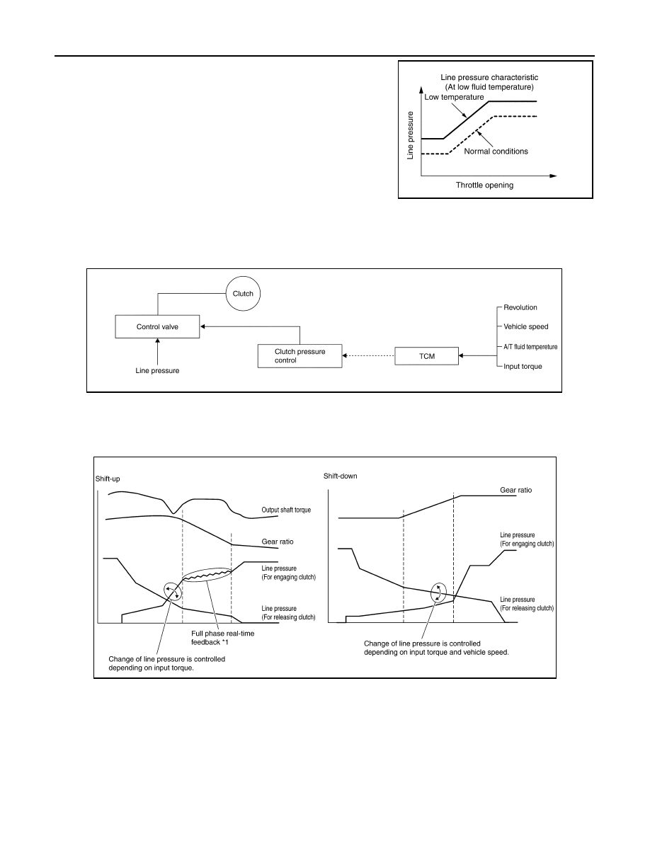
• When the A/T fluid temperature drops below the prescribed tem-

perature, in order to speed up the action of each friction element,
the line pressure is set higher than the normal line pressure char-
acteristic.

SHIFT CONTROL

The clutch pressure control solenoid is controlled by the signals from the switches and sensors. Thus, the
clutch pressure is adjusted to be appropriate to the engine load state and vehicle driving state. It becomes
possible to finely control the clutch hydraulic pressure with high precision and a smoother shift change charac-
teristic is attained.

Shift Change

The clutch is controlled with the optimum timing and oil pressure by the engine speed, engine torque informa-
tion, etc.

Shift Change System Diagram

*1: Full phase real-time feedback control monitors movement of gear ratio at gear change, and controls oil
pressure at real-time to achieve the best gear ratio.

Blipping Control

This system makes transmission clutch engage readily by controlling (synchronizing) engine revolution
according to the (calculation of) engine revolution after shifting down.
• “BLIPPING CONTROL” functions.
- When downshifting by accelerator pedal depression at “D” position.
- When downshifting under the manual mode.
• TCM selects “BLIPPING CONTROL” or “NORMAL SHIFT CONTROL” according to the gear position, the

selector lever position, the engine torque and the speed when accelerating by pedal depression.

PCIA0011E

PCIA0012E

PCIA0013E

A/T CONTROL SYSTEM

TM-85

< FUNCTION DIAGNOSIS >

[5AT: RE5R05A]

C

E

F

G

H

I

J

K

L

M

A

B

TM

N

O

P

• Revolution control demand signal is transmitted from TCM to ECM under “BLIPPING CONTROL”.
• TCM synchronizes engine revolution according to the revolution control demand signal.

Shift Change System Diagram

ASC (Adoptive Shift Control)

ASC automatically shifts or hold at the 2nd, 3rd or 4th gear on certain roads (up/down slope and curve) and
driving condition.

When Driving On an Up/Down Slope

• ASC judges up/down slope according to engine torque data transmitted from the ECM and vehicle speed.

Holding gear at the 3rd or 4th on an up-slope prevents shift hunting and controls the vehicle to gain optimum
driving force. On a down-slope, automatic shift-down to the 3rd or 4th gear controls to gain optimum engine
brake.

When Driving On a Curve

• TCM receives the lateral G sensor signal from the ABS actuator control unit. It locks the gear to the 3rd or

4th position in moderate cornering or to the 2nd position in sharp cornering based on this signal. This pre-
vents any upshift and kickdown during cornering, maintaining smooth vehicle travel.

DS Mode

• Changes to the shift schedule that mainly utilizes the high engine speed zone when ASC is active.
• DS mode can be switched according to the following method.
- When the selector lever is in the “D” position, shifting the selector lever to manual shift gate enables switch-

ing to DS mode.

- When in DS mode, shifting the selector lever to the main gate enables to cancel DS mode.

SCIA6483E

SCIA6469E

TM-86

< FUNCTION DIAGNOSIS >

[5AT: RE5R05A]

A/T CONTROL SYSTEM

- After switching to manual mode with paddle shifter, switching to DS mode can not be enabled even when the

selector lever is shifted to the manual gate. (With paddle shifter)

LOCK-UP CONTROL

The torque converter clutch piston in the torque converter is engaged to eliminate torque converter slip to
increase power transmission efficiency.
The torque converter clutch control valve operation is controlled by the torque converter clutch solenoid valve,
which is controlled by a signal from TCM, and the torque converter clutch control valve engages or releases
the torque converter clutch piston.

Lock-up operation condition table

Torque Converter Clutch Control Valve Control

Lock-up control system diagram

Lock-up Released

• In the lock-up released state, the torque converter clutch control valve is set into the unlocked state by the

torque converter clutch solenoid and the lock-up apply pressure is drained.
In this way, the torque converter clutch piston is not coupled.

Lock-up Applied

• In the lock-up applied state, the torque converter clutch control valve is set into the locked state by the

torque converter clutch solenoid and lock-up apply pressure is generated.
In this way, the torque converter clutch piston is pressed and coupled.

Smooth Lock-up Control

When shifting from the lock-up released state to the lock-up applied state, the current output to the torque con-
verter clutch solenoid is controlled with the TCM. In this way, when shifting to the lock-up applied state, the
torque converter clutch is temporarily set to the half-clutched state to reduce the shock.

Half-clutched State

• The current output from the TCM to the torque converter clutch solenoid is varied to steadily increase the

torque converter clutch solenoid pressure.
In this way, the lock-up apply pressure gradually rises and while the torque converter clutch piston is put into
half-clutched states, the torque converter clutch piston operating pressure is increased and the coupling is
completed smoothly.

Slip Lock-up Control

• In the slip region, the torque converter clutch solenoid current is controlled with the TCM to put it into the

half-clutched state. This absorbs the engine torque fluctuation and lock-up operates from low speed.
This raises the fuel efficiency for 3rd, 4th and 5th gears at both low speed and when the accelerator has a
low degree of opening.

ENGINE BRAKE CONTROL

• The forward one-way clutch transmits the drive force from the engine to the rear wheels. But the reverse

drive from the rear wheels is not transmitted to the engine because the one-way clutch is idling.
Therefore, the low coast brake solenoid is operated to prevent the forward one-way clutch from idling and
the engine brake is operated in the same manner as conventionally.

Selector lever

“D” position

“M” position

Gear  position

5

4

3

5

4

3

Lock-up

×

×

×

×

Slip lock-up

×

×

×

PCIA0014E

A/T CONTROL SYSTEM

TM-87

< FUNCTION DIAGNOSIS >

[5AT: RE5R05A]

C

E

F

G

H

I

J

K

L

M

A

B

TM

N

O

P

• The operation of the low coast brake solenoid switches the low coast brake switching valve and controls the

coupling and releasing of the low coast brake.
The low coast brake reducing valve controls the low coast brake coupling force.

Component Parts Location

INFOID:0000000000956998

SCIA1520E


Content   ..  1346  1347  1348  1349   ..