Infiniti G35 (V35) Sedan. Manual - part 1346


  Index      Infiniti     Infiniti G35 (V35) Sedan - service repair manual 2007 year


Search            


Content   ..  1344  1345  1346  1347   ..


Infiniti G35 (V35) Sedan. Manual - part 1346


TM-76

< SERVICE DATA AND SPECIFICATIONS (SDS) 

[6MT: FS6R31A]

SERVICE DATA AND SPECIFICATIONS (SDS)

Unit: mm (in)

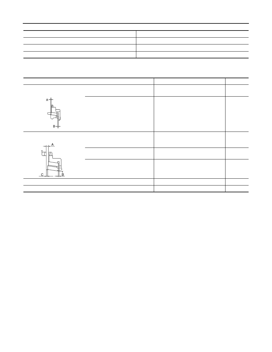
Baulk Ring Clearance

INFOID:0000000000956993

Unit: mm (in)

Item

Standard value

Counter shaft

0 - 0.10 (0 - 0.004)

Main drive gear

0 - 0.10 (0 - 0.004)

Mainshaft

0 - 0.10 (0 - 0.004)

Measurement point

Standard value

Limit value

4th
(Double-cone synchronizer)

Clearance between synchronizer cone 
and inner baulk ring end face “A” 

0.50 - 0.70 (0.020 - 0.028)

0.3 (0.012)

Clearance between outer baulk ring 
pawl and synchronizer cone “B”

0.85 - 1.35 (0.033 -0.053)

0.7 (0.028)

1st, 2nd, and 3rd
(Triple-cone synchronizer)

Clearance between synchronizer cone 
and clutch gear end face “A”

1st: 0.65 - 1.25 (0.026 - 0.049)

2nd: 0.60 - 1.30 (0.024 - 0.051)

3rd: 0.60 - 1.30 (0.024 - 0.051)

0.3 (0.012)
0.3 (0.012)
0.3 (0.012)

Clearance between outer baulk ring 
pawl and synchronizer cone “B”

0.85 - 1.35 (0.033 - 0.053)

0.7 (0.028)

Clearance between inner baulk ring 
and clutch gear end face “C”

1st: 0.80 - 1.2 (0.031 - 0.047)

2nd: 0.75 - 1.25 (0.030 - 0.049)

3rd: 0.75 - 1.25 (0.030 - 0.049)

0.3 (0.012)
0.3 (0.012)
0.3 (0.012)

5th and 6th

0.70 - 1.35 (0.028 - 0.053)

0.5 (0.020)

Reverse

0.75 - 1.20 (0.030 - 0.047)

0.5 (0.020)

PCIB0249E

PCIB0835J

DIAGNOSIS AND REPAIR WORKFLOW

TM-77

< BASIC INSPECTION >

[5AT: RE5R05A]

C

E

F

G

H

I

J

K

L

M

A

B

TM

N

O

P

BASIC INSPECTION

DIAGNOSIS AND REPAIR WORKFLOW

Work Flow

INFOID:0000000000956994

INTRODUCTION

The TCM receives a signal from the vehicle speed sensor, accelera-
tor pedal position sensor (throttle position sensor) or PNP switch and
provides shift control or lock-up control via A/T solenoid valves.
The TCM also communicates with the ECM by means of a signal
sent from sensing elements used with the OBD-related parts of the
A/T system for malfunction-diagnostic purposes. The TCM is capa-
ble of diagnosing malfunctioning parts while the ECM can store mal-
functions in its memory.
Input and output signals must always be correct and stable in the
operation of the A/T system. The A/T system must be in good oper-
ating condition and be free of valve seizure, solenoid valve malfunc-
tion, etc.

It is much more difficult to diagnose a error that occurs intermittently
rather than continuously. Most intermittent errors are caused by poor
electric connections or improper wiring. In this case, careful check-
ing of suspected circuits may help prevent the replacement of good
parts.
A visual check only may not find the cause of the errors. A road test
with CONSULT-III (or GST) or a circuit tester connected should be
performed. Follow the “DETAILED FLOW”.

Before undertaking actual checks, take a few minutes to talk with a
customer who approaches with a driveability complaint. The cus-
tomer can supply good information about such errors, especially
intermittent ones. Find out what symptoms are present and under
what conditions they occur. A “Diagnostic work sheet” as shown on
the example (Refer to 

TM-78

) should be used.

Start your diagnosis by looking for “conventional” errors first. This will
help troubleshoot driveability errors on an electronically controlled
engine vehicle.
Also check related Service bulletins.

DETAILED FLOW

1.

COLLECT THE INFORMATION FROM THE CUSTOMER

Get the detailed information from the customer about the symptom (the condition and the environment when
the incident/malfunction occurred) using diagnosis worksheet. Refer to 

TM-78, "Diagnostic Work Sheet"

.

>> GO TO 2.

2.

CHECK SYMPTOM 1

Check the following items based on the information obtained from the customer.
• Fail-safe. Refer to 

TM-187, "Fail-Safe"

.

• A/T fluid inspection. Refer to 

TM-217, "Inspection"

.

• Line pressure test. Refer to 

TM-224, "Inspection and Judgment"

.

• Stall test. Refer to 

TM-224, "Inspection and Judgment"

.

SAT631IB

SAT632I

SEF234G

TM-78

< BASIC INSPECTION >

[5AT: RE5R05A]

DIAGNOSIS AND REPAIR WORKFLOW

>> GO TO 3.

3.

CHECK DTC

1.

Check DTC.

2.

Perform the following procedure if DTC is detected.

• Record DTC.
• Erase DTC. Refer to 

TM-110, "Diagnosis Description"

.

Is any DTC detected?

YES

>> GO TO 4.

NO

>> GO TO 5.

4.

PERFORM DIAGNOSTIC PROCEDURE

Perform “Diagnostic Procedure” for the displayed DTC.

>> GO TO 5.

5.

CHECK SYMPTOM 2

Try to confirm the symptom described by the customer.

Is any malfunction present?

YES

>> GO TO 6.

NO

>> INSPECTION END

6.

RODE TEST

Perform “RODE TEST”. Refer to 

TM-226, "Description"

.

>> GO TO 7.

7.

CHECK SYMPTOM 3

Try to confirm the symptom described by the customer.

Is any malfunction present?

YES

>> GO TO 2.

NO

>> INSPECTION END

Diagnostic Work Sheet

INFOID:0000000000956995

INFORMATION FROM CUSTOMER

KEY POINTS

• WHAT..... Vehicle and A/T model
• WHEN..... Date, Frequencies
• WHERE..... Road conditions
• HOW..... Operating conditions, Symptoms

Customer name

MR/MS

Model and Year

VIN

Trans. Model

Engine

Mileage

Malfunction Date

Manuf. Date

In Service Date

Frequency

❏

 Continuous

❏

 Intermittent (

times a day)

DIAGNOSIS AND REPAIR WORKFLOW

TM-79

< BASIC INSPECTION >

[5AT: RE5R05A]

C

E

F

G

H

I

J

K

L

M

A

B

TM

N

O

P

DIAGNOSTIC WORK SHEET

Symptoms

❏

 Vehicle does not move.

(

❏

 Any position

❏

 Particular position)

❏

 No up-shift

(

❏

 1st 

→

 2nd

❏

 2nd 

→

 3rd

❏

 3rd 

→

 4th   

❏

 4th 

→

 5th)

❏

 No down-shift

(

❏

 5th 

→

 4th   

❏

 4th 

→

 3rd

❏

 3rd 

→

 2nd

❏

 2nd 

→

 1st)

❏

 Lock-up malfunction

❏

 Shift point too high or too low.

❏

 Shift shock or slip

(

❏

 N 

→

 D

❏

 N 

→

 R

❏

 Lock-up

❏

 Any drive position)

❏

 Noise or vibration

❏

 No kick down

❏

 No pattern select

❏

 Others

(

)

A/T CHECK indicator lamp

❏

 Continuously lit

❏

 Not lit

Malfunction indicator lamp (MIL)

❏

 Continuously lit

❏

 Not lit

1

o Read the item on cautions concerning fail-safe and understand the customer's com-
plaint.

TM-187

2

❏

 A/T fluid inspection, stall test and line pressure test

❏

 A/T fluid inspection

TM-217

❏

 Leak (Repair leak location.)

❏

 State

❏

 Amount

❏

 Stall test

TM-223

❏

 Torque converter one-way clutch

❏

 Front brake

❏

 High and low reverse clutch

❏

 Low coast brake

❏

 Forward brake

❏

 Reverse brake

❏

 Forward one-way clutch

❏

 1st one-way 

clutch

❏

 3rd one-way 

clutch

❏

 Engine

❏

 Line pressure low

❏

 Except for input 

clutch and direct 
clutch, clutches and 
brakes OK

❏

 Line pressure test - Suspected part:

TM-224

3

❏

 Perform self-diagnosis. — Check detected items to repair or replace malfunctioning 

part.

TM-114

4

❏

 Perform rode test.

5-1

❏

 Check before engine is started

TM-226

5-2

❏

 Check at idle

TM-226

5-3

Cruise test

❏

 Part 1

TM-227

❏

 Part 2

TM-228

❏

 Part 3

TM-228

❏

 After completing all rode test, check malfunction phenomena to repair or replace malfunctioning part.

Refer to 

TM-191, "Symptom Table"

.

5

❏

 Drive vehicle to check that the malfunction phenomenon has been resolved.

6

❏

 Erase the results of the self-diagnosis from the TCM and the ECM.

TM-110


Content   ..  1344  1345  1346  1347   ..