Infiniti G35 (V35) Sedan. Manual - part 14


  Index      Infiniti     Infiniti G35 (V35) Sedan - service repair manual 2007 year


Search            


Content   ..  12  13  14  15   ..


Infiniti G35 (V35) Sedan. Manual - part 14


ADP-50

< FUNCTION DIAGNOSIS >

DIAGNOSIS SYSTEM (DRIVER SEAT C/U)

WORK SUPPORT

NOTE:
This mode is only for AT model.

TELESCO MOTOR

Activates/deactivates the telescopic motor.

MIRROR MOTOR RH

Activates/deactivates the mirror motor (passenger side).

MIRROR MOTOR LH

Activates/deactivates the mirror motor (driver side).

MEMORY SW INDCTR

Turns ON/OFF the memory indicator.
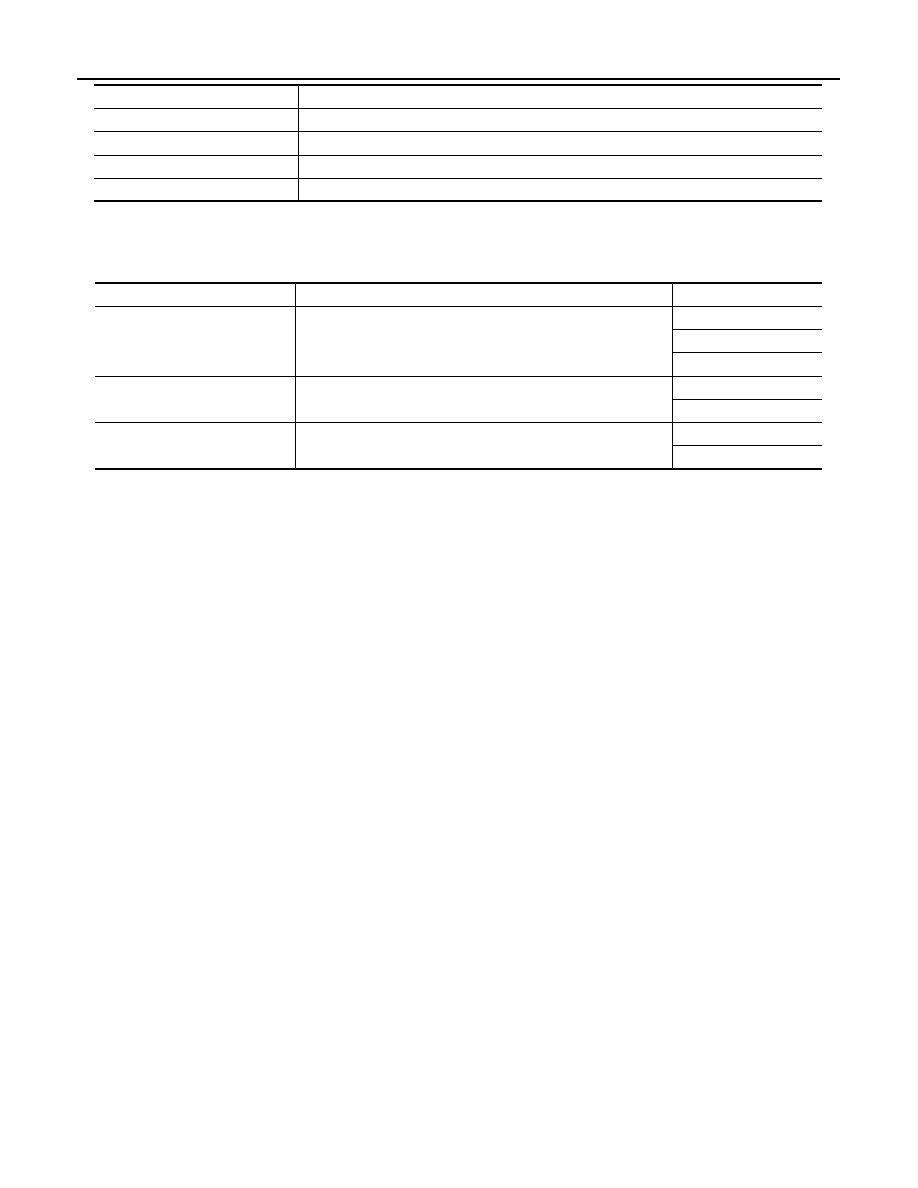
Test item

Description

Work item

Content

Item

SEAT SLIDE VOLUME SET

The amount of seat sliding for entry/exit assist can be selected 
from 3 items.

40 mm

80 mm

150 mm

EXIT TILT SETTING

Entry/exit assist (steering column) can be selected: 
ON (operated) – OFF (not operated)

ON

OFF

EXIT SEAT SLIDE SETTING

Entry/exit assist (seat) can be selected: 
ON (operated) – OFF (not operated)

ON

OFF

U1000 CAN COMM CIRCUIT

ADP-51

< COMPONENT DIAGNOSIS >

C

D

E

F

G

H

I

K

L

M

A

B

ADP

N

O

P

COMPONENT DIAGNOSIS

U1000 CAN COMM CIRCUIT

Description

INFOID:0000000000960620

CAN (Controller Area Network) is a serial communication line for real time applications. It is an on-vehicle mul-
tiplex communication line with high data communication speed and excellent error detection ability. Modern
vehicle is equipped with many electronic control unit, and each control unit shares information and links with
other control units during operation (not independent). In CAN communication, control units are connected
with 2 communication lines (CAN H-line, CAN L-line) allowing a high rate of information transmission with less
wiring. Each control unit transmits/receives data but selectively reads required data only.
CAN Communication Signal Chart. Refer to 

LAN-28, "CAN Communication Signal Chart"

.

DTC Logic

INFOID:0000000000960621

DTC DETECTION LOGIC

DTC CONFIRMATION PROCEDURE

1.

STEP 1

Turn ignition switch ON and wait at least 3 seconds.

>> GO TO 2.

2.

STEP 2

Check “Self diagnostic result” with CONSULT-III.

Is the DTC detected?

YES

>> Perform diagnosis procedure. Refer to 

ADP-51, "Diagnosis Procedure"

.

NO

>> INSPECTION END

Diagnosis Procedure

INFOID:0000000000960622

Refer to 

LAN-18, "Trouble Diagnosis Flow Chart"

.

Special Repair Requirement

INFOID:0000000000960623

Refer to 

ADP-9, "SYSTEM INITIALIZATION : Description"

.

DTC

Trouble diagnosis 

name

DTC detecting condition

Possible cause

U1000

CAN COMM CIR-
CUIT

• Driver seat control unit cannot communicate to other 

control units.

• Driver seat control unit cannot communicate for more 

than the specified time.

• Harness or connectors

(CAN communication line is 
open or shorted)

ADP-52

< COMPONENT DIAGNOSIS >

B2112 SLIDING MOTOR

B2112 SLIDING MOTOR

Description

INFOID:0000000000960624

• The seat sliding motor is installed to the seat cushion frame.
• The seat sliding motor is installed with the driver seat control unit.
• Slides the seat frontward/ rearward by changing the rotation direction of sliding motor.

DTC Logic

INFOID:0000000000960625

DTC DETECTION LOGIC

DTC CONFIRMATION PROCEDURE

1.

STEP 1

Turn ignition switch ON.

>> GO TO 2.

2.

STEP 2

Check “Self diagnostic result” with CONSULT-III.

Is the DTC detected? 

YES

>> Perform diagnosis procedure. Refer to 

ADP-52, "Diagnosis Procedure"

.

NO

>> INSPECTION END

NOTE:
First perform diagnosis for B2126 or B2127 if B2126 or B2127 is detected.

Diagnosis Procedure

INFOID:0000000000960626

1.

PERFORM DTC CONFIRMATION PROCEDURE

1.

Turn ignition switch ON.

2.

Check “Self diagnostic result” with CONSULT-III.

3.

Erase the DTC.

4.

Perform DTC confirmation procedure. Refer to 

ADP-52, "DTC Logic"

.

Is the DTC displayed again?

YES

>> GO TO 2.

NO

>> Check intermittent incident. Refer to 

GI-39, "Intermittent Incident"

.

2.

REPLACE DRIVER SEAT CONTROL UNIT

Replace driver seat control unit. Refer to 

ADP-217, "Removal and Installation"

.

>> INSPECTION END

DTC No.

Trouble diagnosis 

name

DTC detecting condition

Possible cause

P2112

SEAT SLIDE

The driver seat control unit detects the output of slid-
ing motor output terminal for 0.1 second or more 
even if the sliding switch is not input.

• Driver seat control unit

B2113 RECLINING MOTOR

ADP-53

< COMPONENT DIAGNOSIS >

C

D

E

F

G

H

I

K

L

M

A

B

ADP

N

O

P

B2113 RECLINING MOTOR

Description

INFOID:0000000000960627

• The seat reclining motor is installed to the seatback frame.
• The seat reclining motor is activated with the driver seat control unit.
• Tilts the seatback frontward/rearward by changing the rotation direction of reclining motor.

DTC Logic

INFOID:0000000000960628

DTC DETECTION LOGIC

DTC CONFIRMATION PROCEDURE

1.

STEP 1

Turn ignition switch ON.

>> GO TO 2.

2.

STEP 2

Check “Self diagnostic result” with CONSULT-III.

Is the DTC detected? 

YES

>> Perform diagnosis procedure. Refer to 

ADP-53, "Diagnosis Procedure"

.

NO

>> INSPECTION END

NOTE:
First perform diagnosis for B2126 or B2127 if B2126 or B2127 is detected.

Diagnosis Procedure

INFOID:0000000000960629

1.

PERFORM DTC CONFIRMATION PROCEDURE

1.

Turn ignition switch ON.

2.

Check “Self diagnostic result” with CONSULT-III.

3.

Erase the DTC.

4.

Perform DTC confirmation procedure. Refer to 

ADP-53, "DTC Logic"

.

Is the DTC displayed again?

YES

>> GO TO 2.

NO

>> Check intermittent incident. Refer to 

GI-39, "Intermittent Incident"

.

2.

REPLACE DRIVER SEAT CONTROL UNIT

Replace driver seat control unit. Refer to 

ADP-217, "Removal and Installation"

.

>> INSPECTION END

DTC No.

Trouble diagnosis 

name

DTC detecting condition

Possible cause

P2113

SEAT RECLINING

The driver seat control unit detects the output of re-
clining motor output terminal for 0.1 second or more 
even if the reclining switch is not input.

• Driver seat control unit


Content   ..  12  13  14  15   ..