Infiniti G20 (P11). Manual - part 489


  Index      Infiniti     Infiniti G20 (P11) - service repair manual 1999-2002 year


Search            


Content   ..  487  488  489  490   ..


Infiniti G20 (P11). Manual - part 489


SMT669DA

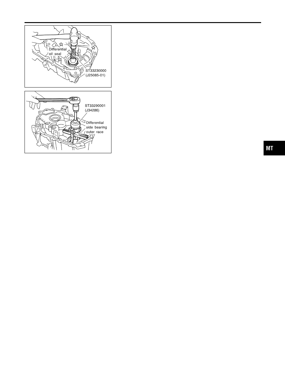
30. Remove differential oil seal from housing.

SMT670DA

31. Remove differential side outer race from housing.

GI

MA

EM

LC

EC

FE

CL

AT

AX

SU

BR

ST

RS

BT

HA

SC

EL

IDX

DISASSEMBLY

Clutch Housing (Cont’d)

MT-25

SMT759D

Input Shaft and Gears

DISASSEMBLY

NCMT0010

1.

Before disassembly, measure the end plays of 3rd and 4th
input gears.

Gear end play:

Refer to SDS, MT-57.

I

If end play is not within specification, disassemble and check
the parts.

SMT671D

2.

Remove oil channel from input shaft rear bearing.

SMT672DA

3.

Press out input shaft rear bearing.

SMT673D

4.

Remove C-ring holder.

5.

Remove 5th gear rear C-ring.

SMT674DA

6.

Remove 5th input gear from input shaft.

7.

Remove 5th gear front C-ring.

REPAIR FOR COMPONENT PARTS

Input Shaft and Gears

MT-26

SMT675DA

8.

Remove 4th input gear, baulk ring, 4th gear needle bearing,
and 4th gear C-ring from input shaft.

9.

Press out both 3rd & 4th synchronizer hub assembly and 3rd
input gear from input shaft.

10. Remove 3rd gear needle bearing.

SMT676DA

11. Press out input shaft front bearing from input shaft.

SMT693D

INSPECTION

NCMT0011

Gear and Shaft

NCMT0011S01

I

Check shaft for cracks, wear or bending.

I

Check gears for excessive wear, chips or cracks.

SMT637A

Synchronizers

NCMT0011S02

I

Check spline area of coupling sleeves, hubs and gears for
wear or cracks.

I

Check baulk rings for cracks or deformation.

I

Check insert springs for wear or deformation.

SMT867D

I

If any crack, damage, or excessive wear is found on cam face
of baulk ring or working face of insert, replace it.

GI

MA

EM

LC

EC

FE

CL

AT

AX

SU

BR

ST

RS

BT

HA

SC

EL

IDX

REPAIR FOR COMPONENT PARTS

Input Shaft and Gears (Cont’d)

MT-27

SMT841D

I

Measure the movement (play, dimension “L”) of 3rd & 4th cou-
pling sleeve with their end fixed and the other end lifted as
shown in the figure. If the movement exceeds specification,
replace the sleeve.

Coupling sleeve

Length “L”

3rd & 4th

0 - 0.95 mm (0 - 0.0374 in)

SMT140

I

Measure clearance between baulk ring and gear.

Clearance between baulk ring and gear:

Refer to SDS, MT-57.

SMT148A

Bearing

NCMT0011S03

I

Make sure bearings roll freely and are free from noise, cracks,
pitting or wear.

SMT696DA

ASSEMBLY

NCMT0012

1.

Press on input shaft front bearing.

2.

Install 3rd gear needle, 3rd input gear and 3rd gear baulk ring
bearing to input shaft.

SMT694D

3.

Install spread spring, shifting insert, and 3rd & 4th synchronizer
hub onto 3rd & 4th coupling sleeve.

I

Pay attention to the shape of spread spring and shifting insert
for correct assembly.
Do not install spread spring hook onto the same shifting insert.

CAUTION:

Do not reuse 3rd & 4th synchronizer hub.

REPAIR FOR COMPONENT PARTS

Input Shaft and Gears (Cont’d)

MT-28


Content   ..  487  488  489  490   ..