Infiniti G20 (P11). Manual - part 421
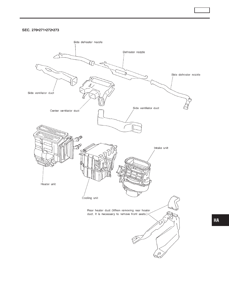
Component Layout
NCHA0012
RHA041H
GI
MA
EM
LC
EC
FE
CL
MT
AT
AX
SU
BR
ST
RS
BT
SC
EL
IDX
DESCRIPTION
AUTO
Component Layout
HA-15
|
|
|
Component Layout NCHA0012 RHA041H GI MA EM LC EC FE CL MT AT AX SU BR ST RS BT SC EL IDX DESCRIPTION AUTO Component Layout HA-15 |