Infiniti G20 (P11). Manual - part 336
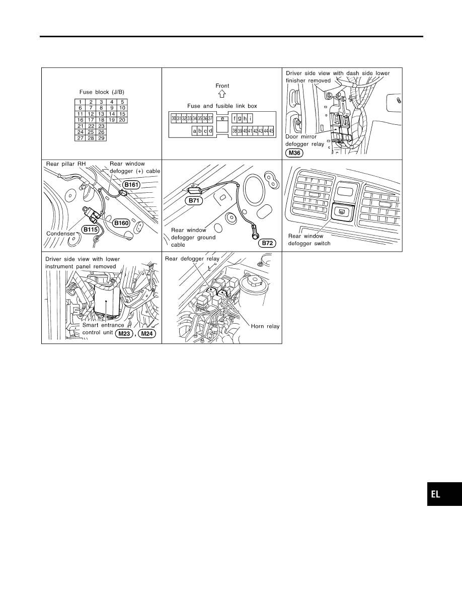
Component Parts and Harness Connector
Location
NCEL0072
SEL667W
System Description
NCEL0073
The rear window defogger system is controlled by the smart entrance control unit. The rear window defogger
operates only for approximately 15 minutes.
Power is supplied at all times
I
to rear window defogger relay terminal 3
I
through 20A fuse (No. 39, located in the fuse and fusible link box) and
I
to rear window defogger relay terminal 6
I
through 20A fuse (No. 40, located in the fuse and fusible link box).
With the ignition switch in the ON or START position, power is supplied
I
through 10A fuse [No. 8, located in the fuse block (J/B)]
I
to the rear window defogger relay terminal 1 and
I
to smart entrance control unit terminal 33.
Ground is supplied to terminal 2 of the rear window defogger switch through body grounds M15, M71 and M76.
When the rear window defogger switch is turned ON, ground is supplied
I
through terminal 1 of the rear window defogger switch
I
to smart entrance control unit terminal 39.
Terminal 2 of the smart entrance control unit then supplies ground to the rear window defogger relay termi-
nal 2.
With power and ground supplied, the rear window defogger relay is energized.
Power is supplied
I
through terminals 5 and 7 of the rear window defogger relay
GI
MA
EM
LC
EC
FE
CL
MT
AT
AX
SU
BR
ST
RS
BT
HA
SC
IDX
REAR WINDOW DEFOGGER
Component Parts and Harness Connector Location
EL-121