Infiniti G20 (P11). Manual - part 293
SEF740W
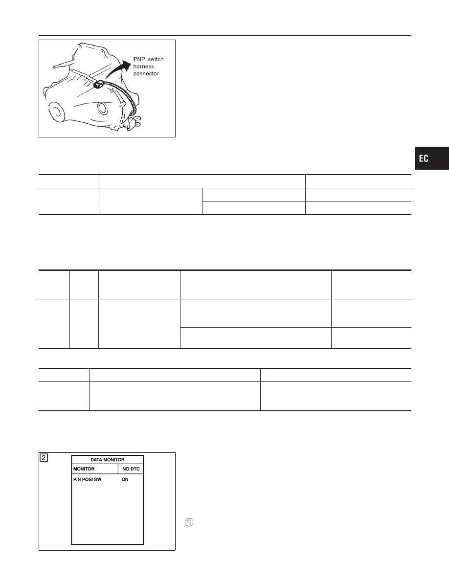
Component Description
NCEC0424
When the gear position is “P” (A/T models only) or “N”, park/neutral
position (PNP) switch is “ON”.
ECM detects the park/neutral position when continuity with ground
exists.
CONSULT-II Reference Value in Data Monitor
Mode
NCEC0425
Specification data are reference values.
MONITOR ITEM
CONDITION
SPECIFICATION
P/N POSI SW
I
Ignition switch: ON
Shift lever: “P” or “N”
ON
Except above
OFF
ECM Terminals and Reference Value
NCEC0426
Specification data are reference values and are measured between each terminal and ground.
CAUTION:
Do not use ECM ground terminals when measuring input/output voltage. Doing so may result in dam-
age to the ECM’s transistor. Use a ground other than ECM terminals, such as the ground.
TERMI-
NAL
NO.
WIRE
COLOR
ITEM
CONDITION
DATA (DC Voltage)
42
G/OR
PNP switch
[Ignition switch “ON”]
I
Gear position is “Neutral position” (M/T models)
I
Gear position is “N” or “P” (A/T models)
Approximately 0V
[Ignition switch “ON”]
I
Except the above gear position
BATTERY VOLTAGE
(11 - 14V)
On Board Diagnosis Logic
NCEC0427
DTC No.
Malfunction is detected when ...
Check Items (Possible Cause)
P1706
I
The signal of the PNP switch is not changed in the pro-
cess of engine starting and driving.
I
Harness or connectors
(The PNP switch circuit is open or shorted.)
I
PNP switch
SEF212Y
DTC Confirmation Procedure
NCEC0428
CAUTION:
Always drive vehicle at a safe speed.
NOTE:
If “DTC Confirmation Procedure” has been previously conducted,
always turn ignition switch “OFF” and wait at least 10 seconds
before conducting the next test.
With CONSULT-II
1)
Turn ignition switch “ON”.
GI
MA
EM
LC
FE
CL
MT
AT
AX
SU
BR
ST
RS
BT
HA
SC
EL
IDX
DTC P1706 PARK/NEUTRAL POSITION (PNP) SWITCH
Component Description
EC-583