Infiniti G20 (P11). Manual - part 289


  Index      Infiniti     Infiniti G20 (P11) - service repair manual 1999-2002 year


Search            


Content   ..  287  288  289  290   ..


Infiniti G20 (P11). Manual - part 289


6

DETECT MALFUNCTIONING PART

Check the following.

I

Harness connectors T19, T20

I

Harness connectors T1, B113

I

Harness connectors B120, B10

I

Harness connectors B3, M8

I

Harness connectors M49, F23

I

Harness for open or short between vacuum cut valve bypass valve and ECM

©

Repair open circuit or short to ground or short to power in harness or connectors.

7

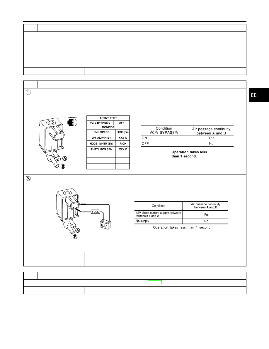
CHECK VACUUM CUT VALVE BYPASS VALVE

With CONSULT-II

1. Reconnect harness disconnected connectors.
2. Turn ignition switch ON.
3. Perform “VC/V BYPASS/V” in “ACTIVE TEST” mode.
4. Check air passage continuity and operation delay time under the following conditions.

SEF807Y

Without CONSULT-II

Check air passage continuity and operation delay time under the following conditions.

SEF557Y

OK or NG

OK

©

GO TO 8.

NG

©

Replace vacuum cut valve bypass valve.

8

CHECK INTERMITTENT INCIDENT

Refer to “TROUBLE DIAGNOSIS FOR INTERMITTENT INCIDENT”, EC-146.

©

INSPECTION END

GI

MA

EM

LC

FE

CL

MT

AT

AX

SU

BR

ST

RS

BT

HA

SC

EL

IDX

DTC P1490 VACUUM CUT VALVE BYPASS VALVE (CIRCUIT)

Diagnostic Procedure (Cont’d)

EC-567

SEF861X

Description

NCEC0630

COMPONENT DESCRIPTION

NCEC0630S01

The vacuum cut valve and vacuum cut valve bypass valve are
installed in parallel on the EVAP purge line between the fuel tank
and the EVAP canister.
The vacuum cut valve prevents the intake manifold vacuum from
being applied to the fuel tank.
The vacuum cut valve bypass valve is a solenoid type valve and
generally remains closed. It opens only for on board diagnosis.
The vacuum cut valve bypass valve responds to signals from the
ECM. When the ECM sends an ON (ground) signal, the valve is
opened. The vacuum cut valve is then bypassed to apply intake
manifold vacuum to the fuel tank.

EVAPORATIVE EMISSION SYSTEM DIAGRAM

NCEC0630S02

SEF323U

CONSULT-II Reference Value in Data Monitor
Mode

NCEC0631

Specification data are reference values.

MONITOR ITEM

CONDITION

SPECIFICATION

VC/V BYPASS/V

I

Ignition switch: ON

OFF

ECM Terminals and Reference Value

NCEC0662

Specification data are reference values and are measured between each terminal and ground.

CAUTION:

Do not use ECM ground terminals when measuring input/output voltage. Doing so may result in dam-
age to the ECM’s transistor. Use a ground other than ECM terminals, such as the ground.

TER-

MINAL

NO.

WIRE

COLOR

ITEM

CONDITION

DATA (DC Voltage)

2

PU/R

Vacuum cut valve
bypass valve

[Ignition switch “ON”]

BATTERY VOLTAGE
(11 - 14V)

DTC P1491 VACUUM CUT VALVE BYPASS VALVE

Description

EC-568

On Board Diagnosis Logic

NCEC0632

Malfunction is detected when vacuum cut valve bypass valve does
not operate properly.

Possible Cause

NCEC0633

I

Vacuum cut valve bypass valve

I

Vacuum cut valve

I

Bypass hoses for clogging

I

EVAP control system pressure sensor and circuit

I

EVAP canister vent control valve

I

Hose between fuel tank and vacuum cut valve clogged

I

Hose between vacuum cut valve and EVAP canister clogged

I

EVAP canister

I

EVAP purge port of fuel tank for clogging

SEF210Y

SEF211Y

SEF239Y

DTC Confirmation Procedure

NCEC0634

CAUTION:

Always drive vehicle at a safe speed.
NOTE:
If “DTC Confirmation Procedure” has been previously conducted,
always turn ignition switch “OFF” and wait at least 10 seconds
before conducting the next test.
TESTING CONDITION:
Always perform test at a temperature of 5 to 30°C (41 to 86°F).

WITH CONSULT-II

NCEC0634S01

1)

Turn ignition switch “ON”.

2)

Start engine and warm it up to normal operating temperature.

3)

Turn ignition switch “OFF” and wait at least 10 seconds.

4)

Start engine and let it idle for at least 70 seconds.

5)

Select “VC CUT/V BP/V P1491” of “EVAPORATIVE SYSTEM”
in “DTC WORK SUPPORT” mode with CONSULT-II.

6)

Touch “START”.

7)

When the following conditions are met, “TESTING” will be dis-
played on the CONSULT-II screen. Maintain the conditions
continuously until “TESTING” changes to “COMPLETED”. (It
will take at least 30 seconds.)

ENG SPEED

More than 1,000 rpm

Selector lever

Suitable position

Vehicle speed

More than 37 km/h (23 MPH)

B/FUEL SCHDL

1.0 – 8.9 msec

If “TESTING” is not displayed after 5 minutes, retry from
step 3.

8)

Make sure that “OK” is displayed after touching “SELF-DIAG
RESULTS”.

If

“NG”

is

displayed,

refer

to

“Diagnostic

Procedure”, EC-572.

GI

MA

EM

LC

FE

CL

MT

AT

AX

SU

BR

ST

RS

BT

HA

SC

EL

IDX

DTC P1491 VACUUM CUT VALVE BYPASS VALVE

On Board Diagnosis Logic

EC-569

SEF530Q

Overall Function Check

NCEC0635

Use this procedure to check the overall function of vacuum cut
valve bypass valve. During this check, the 1st trip DTC might not
be confirmed.

WITH GST

NCEC0635S01

1)

Remove vacuum cut valve and vacuum cut valve bypass valve
as an assembly.

2)

Apply vacuum to port and check that there is no suction from
port B.

3)

Apply vacuum to port and check that there is suction from
port A.

4)

Blow air in port and check that there is a resistance to flow
out of port A.

5)

Supply battery voltage to the terminal.

6)

Blow air in port and check that air flows freely out of port B.

7)

Blow air in port and check that air flows freely out of port A.

8)

If NG, go to “Diagnostic Procedure”, EC-572.

DTC P1491 VACUUM CUT VALVE BYPASS VALVE

Overall Function Check

EC-570


Content   ..  287  288  289  290   ..