Infiniti G20 (P11). Manual - part 170


  Index      Infiniti     Infiniti G20 (P11) - service repair manual 1999-2002 year


Search            


Content   ..  168  169  170  171   ..


Infiniti G20 (P11). Manual - part 170


FUNCTION

=NCEC0504S03

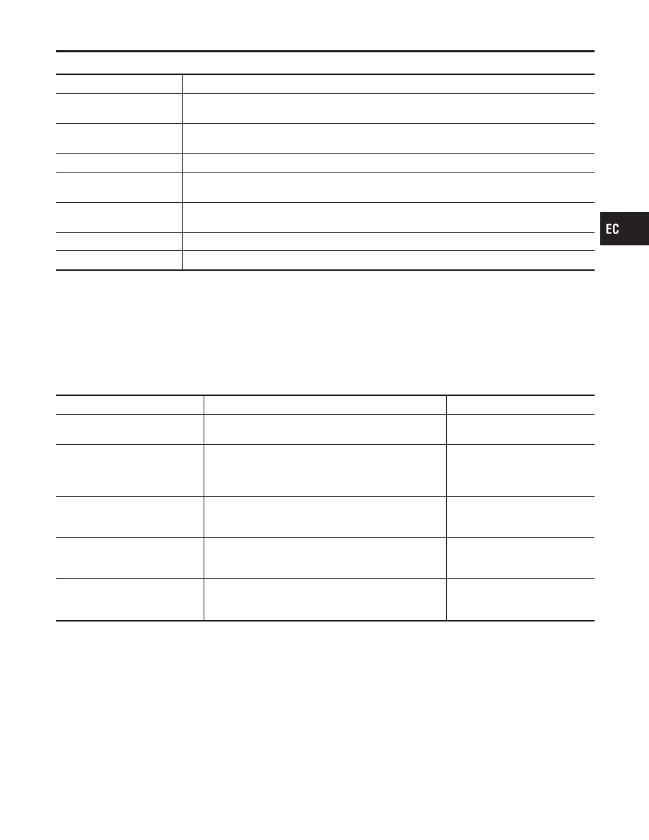
Diagnostic test mode

Function

Work support

This mode enables a technician to adjust some devices faster and more accurately by following the
indications on the CONSULT-II unit.

Self-diagnostic results

Self-diagnostic results such as 1st trip DTC, DTCs and 1st trip freeze frame data or freeze frame
data can be read and erased quickly.*1

Data monitor

Input/Output data in the ECM can be read.

Data monitor (SPEC)

Input/Output specification of the Basic fuel schedule, AFM, A/F feedback control value and the
other data monitor items can be read.

Active test

Diagnostic Test Mode in which CONSULT-II drives some actuators apart from the ECMs and also
shifts some parameters in a specified range.

DTC & SRT confirmation

The status of system monitoring tests and the self-diagnosis status/result can be confirmed.

ECM part number

ECM part number can be read.

*1 The following emission-related diagnostic information is cleared when the ECM memory is erased.
1)

Diagnostic trouble codes

2)

1st trip diagnostic trouble codes

3)

Freeze frame data

4)

1st trip freeze frame data

5)

System readiness test (SRT) codes

6)

Test values

7)

Others

WORK SUPPORT MODE

NCEC0504S04

WORK ITEM

CONDITION

USAGE

TP SW/TP SEN IDLE POSI ADJ

I

FOLLOW THE BASIC INSPECTION IN THE SERVICE
MANUAL.

When adjusting the idle throttle
position.

IGNITION TIMING ADJ

I

IGNITION TIMING FEEDBACK CONTROL WILL BE
HELD BY TOUCHING “START”. AFTER DOING SO,
ADJUST IGNITION TIMING WITH A TIMING LIGHT BY
TURNING THE CAMSHAFT POSITION SENSOR.

When adjusting initial ignition tim-
ing

FUEL PRESSURE RELEASE

I

FUEL PUMP WILL STOP BY TOUCHING “START”
DURING IDLING.
CRANK A FEW TIMES AFTER ENGINE STALLS.

When releasing fuel pressure
from fuel line

IDLE AIR VOL LEARN

I

THE IDLE AIR VOLUME THAT KEEPS THE ENGINE
WITHIN THE SPECIFIED RANGE IS MEMORIZED IN
ECM.

When learning the idle air volume

SELF-LEARNING CONT

I

THE COEFFICIENT OF SELF-LEARNING CONTROL
MIXTURE RATIO RETURNS TO THE ORIGINAL
COEFFICIENT.

When clearing the coefficient of
self-learning control value

GI

MA

EM

LC

FE

CL

MT

AT

AX

SU

BR

ST

RS

BT

HA

SC

EL

IDX

ON BOARD DIAGNOSTIC SYSTEM DESCRIPTION

CONSULT-II (Cont’d)

EC-91

WORK ITEM

CONDITION

USAGE

EVAP SYSTEM CLOSE

OPEN THE VACUUM CUT VALVE BYPASS VALVE AND
CLOSE THE EVAP CANISTER VENT CONTROL VALVE
IN ORDER TO MAKE EVAP SYSTEM CLOSE UNDER
THE FOLLOWING CONDITIONS.

I

IGN SW “ON”

I

ENGINE NOT RUNNING

I

AMBIENT TEMPERATURE IS ABOVE 0°C (32°F).

I

NO VACUUM AND NO HIGH PRESSURE IN EVAP
SYSTEM

I

TANK FUEL TEMP. IS MORE THAN 0°C (32°F).

I

WITHIN 10 MINUTES AFTER STARTING “EVAP SYS-
TEM CLOSE”

I

WHEN TRYING TO EXECUTE “EVAP SYSTEM
CLOSE” UNDER THE CONDITION EXCEPT ABOVE,
CONSULT-II WILL DISCONTINUE IT AND DISPLAY
APPROPRIATE INSTRUCTION.
NOTE:
WHEN STARTING ENGINE, CONSULT-II MAY DIS-
PLAY “BATTERY VOLTAGE IS LOW. CHARGE
BATTERY”, EVEN IN USING CHARGED BATTERY.

When detecting EVAP vapor leak
point of EVAP system

TARGET IDLE RPM ADJ*

I

IDLE CONDITION

When setting target idle speed

*: This function is not necessary in the usual service procedure.

ON BOARD DIAGNOSTIC SYSTEM DESCRIPTION

CONSULT-II (Cont’d)

EC-92

SELF-DIAGNOSTIC MODE

=NCEC0504S05

DTC and 1st Trip DTC

NCEC0504S0501

Regarding items of “DTC and 1st trip DTC”, refer to “TROUBLE
DIAGNOSIS — INDEX” (See EC-8.)

Freeze Frame Data and 1st Trip Freeze Frame Data

NCEC0504S0502

Freeze frame data

item*1

Description

DIAG TROUBLE
CODE
[PXXXX]

I

The engine control component part/control system has a trouble code, it is displayed as “PXXXX”.
(Refer to “TROUBLE DIAGNOSIS — INDEX”, EC-8.)

FUEL SYS-B1

I

“Fuel injection system status” at the moment a malfunction is detected is displayed.

I

One mode in the following is displayed.
“MODE 2”: Open loop due to detected system malfunction
“MODE 3”: Open loop due to driving conditions (power enrichment, deceleration enrichment)
“MODE 4”: Closed loop - using oxygen sensor(s) as feedback for fuel control
“MODE 5”: Open loop - has not yet satisfied condition to go to closed loop

CAL/LD VALUE [%]

I

The calculated load value at the moment a malfunction is detected is displayed.

COOLANT TEMP [°C]
or [°F]

I

The engine coolant temperature at the moment a malfunction is detected is displayed.

S-FUEL TRIM-B1 [%]

I

“Short-term fuel trim” at the moment a malfunction is detected is displayed.

I

The short-term fuel trim indicates dynamic or instantaneous feedback compensation to the base fuel
schedule.

L-FUEL TRIM-B1 [%]

I

“Long-term fuel trim” at the moment a malfunction is detected is displayed.

I

The long-term fuel trim indicates much more gradual feedback compensation to the base fuel schedule
than short-term fuel trim.

ENGINE SPEED
[rpm]

I

The engine speed at the moment a malfunction is detected is displayed.

VHCL SPEED [km/h]
or [mph]

I

The vehicle speed at the moment a malfunction is detected is displayed.

ABSOL TH-P/S [%]

I

The throttle valve opening angle at the moment a malfunction is detected is displayed.

B/FUEL SCHDL
[msec]

I

The base fuel schedule at the moment a malfunction is detected is displayed.

INT/A TEMP SE [°C]
or [°F]

I

The intake air temperature at the moment a malfunction is detected is displayed.

*1: The items are the same as those of 1st trip freeze frame data.

GI

MA

EM

LC

FE

CL

MT

AT

AX

SU

BR

ST

RS

BT

HA

SC

EL

IDX

ON BOARD DIAGNOSTIC SYSTEM DESCRIPTION

CONSULT-II (Cont’d)

EC-93

DATA MONITOR MODE

=NCEC0504S06

Monitored item [Unit]

ECM
input

signals

Main

signals

Description

Remarks

ENG SPEED [rpm]

q

q

I

Indicates the engine speed computed
from the REF signal (180° signal) of the
camshaft position sensor.

MAS A/F SE-B1 [V]

q

q

I

The signal voltage of the mass air flow
sensor is displayed.

I

When the engine is stopped, a certain
value is indicated.

B/FUEL SCHDL
[msec]

I

“Base fuel schedule” indicates the fuel
injection pulse width programmed into
ECM, prior to any learned on board
correction.

A/F ALPHA-B1 [%]

q

I

The mean value of the air-fuel ratio
feedback correction factor per cycle is
indicated.

I

When the engine is stopped, a certain
value is indicated.

I

This data also includes the data for the
air-fuel ratio learning control.

COOLAN TEMP/S
[°C] or [°F]

q

q

I

The engine coolant temperature (deter-
mined by the signal voltage of the
engine coolant temperature sensor) is
displayed.

I

When the engine coolant temperature
sensor is open or short-circuited, ECM
enters fail-safe mode. The engine cool-
ant temperature determined by the
ECM is displayed.

HO2S1 (B1) [V]

q

q

I

The signal voltage of the heated oxy-
gen sensor 1 (front) is displayed.

HO2S2 (B1) [V]

q

q

I

The signal voltage of the heated oxy-
gen sensor 2 (rear) is displayed.

HO2S1 MNTR (B1)
[RICH/LEAN]

q

I

Display of heated oxygen sensor 1
(front) signal during air-fuel ratio feed-
back control:
RICH ... means the mixture became
“rich”, and control is being affected
toward a leaner mixture.
LEAN ... means the mixture became
“lean”, and control is being affected
toward a rich mixture.

I

After turning ON the ignition switch,
“RICH” is displayed until air-fuel mixture
ratio feedback control begins.

I

When the air-fuel ratio feedback is
clamped, the value just before the
clamping is displayed continuously.

HO2S2 MNTR (B1)
[RICH/LEAN]

q

I

Display of heated oxygen sensor 2
(rear) signal:
RICH ... means the amount of oxygen
after three way catalyst is relatively
small.
LEAN ... means the amount of oxygen
after three way catalyst is relatively
large.

I

When the engine is stopped, a certain
value is indicated.

VHCL SPEED SE
[km/h] or [mph]

q

q

I

The vehicle speed computed from the
vehicle speed sensor signal is dis-
played.

BATTERY VOLT [V]

q

q

I

The power supply voltage of ECM is
displayed.

THRTL POS SEN [V]

q

q

I

The throttle position sensor signal volt-
age is displayed.

FUEL T/TMP SE
[°C] or [°F]

q

I

The fuel temperature judged from the
tank fuel temperature sensor signal
voltage is displayed.

ON BOARD DIAGNOSTIC SYSTEM DESCRIPTION

CONSULT-II (Cont’d)

EC-94


Content   ..  168  169  170  171   ..