Infiniti G20 (P11). Manual - part 168


  Index      Infiniti     Infiniti G20 (P11) - service repair manual 1999-2002 year


Search            


Content   ..  166  167  168  169   ..


Infiniti G20 (P11). Manual - part 168


OBD System Operation Chart

=NCEC0033

RELATIONSHIP BETWEEN MIL, 1ST TRIP DTC, DTC, AND DETECTABLE ITEMS

NCEC0033S01

I

When a malfunction is detected for the first time, the 1st trip DTC and the 1st trip freeze frame data are
stored in the ECM memory.

I

When the same malfunction is detected in two consecutive trips, the DTC and the freeze frame data are
stored in the ECM memory, and the MIL will come on. For details, refer to “Two Trip Detection Logic” on
EC-67.

I

The MIL will go off after the vehicle is driven 3 times with no malfunction. The drive is counted only when
the recorded driving pattern is met (as stored in the ECM). If another malfunction occurs while counting,
the counter will reset.

I

The DTC and the freeze frame data will be stored until the vehicle is driven 40 times (driving pattern A)
without the same malfunction recurring (except for Misfire and Fuel Injection System). For Misfire and Fuel
Injection System, the DTC and freeze frame data will be stored until the vehicle is driven 80 times (driv-
ing pattern C) without the same malfunction recurring. The “TIME” in “SELF-DIAGNOSTIC RESULTS”
mode of CONSULT-II will count the number of times the vehicle is driven.

I

The 1st trip DTC is not displayed when the self-diagnosis results in “OK” for the 2nd trip.
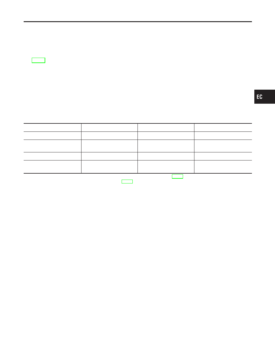
SUMMARY CHART

NCEC0033S02

Items

Fuel Injection System

Misfire

Other

MIL (goes off)

3 (pattern B)

3 (pattern B)

3 (pattern B)

DTC, Freeze Frame Data (no
display)

80 (pattern C)

80 (pattern C)

40 (pattern A)

1st Trip DTC (clear)

1 (pattern C), *1

1 (pattern C), *1

1 (pattern B)

1st Trip Freeze Frame Data
(clear)

*1, *2

*1, *2

1 (pattern B)

For details about patterns “B” and “C” under “Fuel Injection System” and “Misfire”, see EC-85.
For details about patterns “A” and “B” under “Other”, see EC-87.
*1: Clear timing is at the moment OK is detected.
*2: Clear timing is when the same malfunction is detected in the 2nd trip.

GI

MA

EM

LC

FE

CL

MT

AT

AX

SU

BR

ST

RS

BT

HA

SC

EL

IDX

ON BOARD DIAGNOSTIC SYSTEM DESCRIPTION

OBD System Operation Chart

EC-83

RELATIONSHIP BETWEEN MIL, DTC, 1ST TRIP DTC AND DRIVING PATTERNS FOR
“MISFIRE” <EXHAUST QUALITY DETERIORATION>, “FUEL INJECTION SYSTEM”

=NCEC0033S03

SEF392S

*1: When the same malfunction is

detected in two consecutive trips,
MIL will light up.

*2: MIL will go off after vehicle is

driven 3 times (pattern B) without
any malfunctions.

*3: When the same malfunction is

detected in two consecutive trips,
the DTC and the freeze frame
data will be stored in ECM.

*4: The DTC and the freeze frame

data will not be displayed any
longer after vehicle is driven 80
times (pattern C) without the same
malfunction.
(The DTC and the freeze frame
data still remain in ECM.)

*5: When a malfunction is detected

for the first time, the 1st trip DTC
and the 1st trip freeze frame data
will be stored in ECM.

*6: The 1st trip DTC and the 1st trip

freeze frame data will be cleared
at the moment OK is detected.

*7: When the same malfunction is

detected in the 2nd trip, the 1st
trip freeze frame data will be
cleared.

*8: 1st trip DTC will be cleared when

vehicle is driven once (pattern C)
without the same malfunction after
DTC is stored in ECM.

ON BOARD DIAGNOSTIC SYSTEM DESCRIPTION

OBD System Operation Chart (Cont’d)

EC-84

EXPLANATION FOR DRIVING PATTERNS FOR “MISFIRE <EXHAUST QUALITY
DETERIORATION>”, “FUEL INJECTION SYSTEM”

=NCEC0033S04

Driving Pattern B

NCEC0033S0401

Driving pattern B means the vehicle operation as follows:
All components and systems should be monitored at least once by the OBD system.

I

The B counter will be cleared when the malfunction is detected once regardless of the driving pattern.

I

The B counter will be counted up when driving pattern B is satisfied without any malfunction.

I

The MIL will go off when the B counter reaches 3. (*2 in “OBD SYSTEM OPERATION CHART”)

Driving Pattern C

NCEC0033S0402

Driving pattern C means the vehicle operation as follows:
1) The following conditions should be satisfied at the same time:

Engine speed: (Engine speed in the freeze frame data)

±

375 rpm

Calculated load value: (Calculated load value in the freeze frame data)

×

(1

±

0.1) [%]

Engine coolant temperature (T) condition:

I

When the freeze frame data shows lower than 70°C (158°F), “T” should be lower than 70°C (158°F).

I

When the freeze frame data shows higher than or equal to 70°C (158°F), “T” should be higher than or
equal to 70°C (158°F).

Example:
If the stored freeze frame data is as follows:
Engine speed: 850 rpm, Calculated load value: 30%, Engine coolant temperature: 80°C (176°F)
To be satisfied with driving pattern C, the vehicle should run under the following conditions:
Engine speed: 475 - 1,225 rpm, Calculated load value: 27 - 33%, Engine coolant temperature: more than 70°C
(158°F)

I

The C counter will be cleared when the malfunction is detected regardless of (1).

I

The C counter will be counted up when (1) is satisfied without the same malfunction.

I

The DTC will not be displayed after C counter reaches 80.

I

The 1st trip DTC will be cleared when C counter is counted once without the same malfunction after DTC
is stored in ECM.

GI

MA

EM

LC

FE

CL

MT

AT

AX

SU

BR

ST

RS

BT

HA

SC

EL

IDX

ON BOARD DIAGNOSTIC SYSTEM DESCRIPTION

OBD System Operation Chart (Cont’d)

EC-85

RELATIONSHIP BETWEEN MIL, DTC, 1ST TRIP DTC AND DRIVING PATTERNS EXCEPT
FOR “MISFIRE <EXHAUST QUALITY DETERIORATION>”, “FUEL INJECTION SYSTEM”

NCEC0033S05

SEF393S

*1: When the same malfunction is

detected in two consecutive trips,
MIL will light up.

*2: MIL will go off after vehicle is

driven 3 times (pattern B) without
any malfunctions.

*3: When the same malfunction is

detected in two consecutive trips,
the DTC and the freeze frame
data will be stored in ECM.

*4: The DTC and the freeze frame

data will not be displayed any
longer after vehicle is driven 40
times (pattern A) without the same
malfunction.
(The DTC and the freeze frame
data still remain in ECM.)

*5: When a malfunction is detected

for the first time, the 1st trip DTC

and the 1st trip freeze frame data
will be stored in ECM.

*6: 1st trip DTC will be cleared after

vehicle is driven once (pattern B)
without the same malfunction.

*7: When the same malfunction is

detected in the 2nd trip, the 1st
trip freeze frame data will be
cleared.

ON BOARD DIAGNOSTIC SYSTEM DESCRIPTION

OBD System Operation Chart (Cont’d)

EC-86


Content   ..  166  167  168  169   ..