Infiniti G20 (P11). Manual - part 167
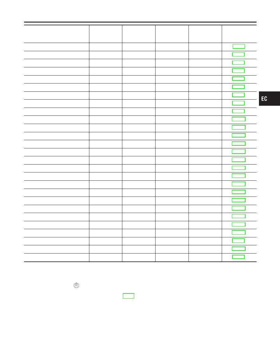
Items
(CONSULT-II screen terms)
DTC*1
SRT code
Test value/ Test
limit
(GST only)
1st trip DTC*1
Reference page
A/T 1ST GR FNCTN
P0731
—
—
X
A/T 2ND GR FNCTN
P0732
—
—
X
A/T 3RD GR FNCTN
P0733
—
—
X
A/T 4TH GR FNCTN
P0734
—
—
X
TCC SOLENOID/CIRC
P0740
—
—
X
A/T TCC S/V FNCTN
P0744
—
—
X
L/PRESS SOL/CIRC
P0745
—
—
X
SFT SOL A/CIRC
P0750
—
—
X
SFT SOL B/CIRC
P0755
—
—
X
THERMOSTAT FNCTN
P1126
—
—
X
CLOSED LOOP-B1
P1148
—
—
X
ENG OVER TEMP
P1217
—
—
X
CKP SENSOR COG
P1336
—
—
X
EGR TEMP SEN/CIRC
P1401
—
—
X
EGR SYSTEM
P1402
X
X
X*2
EVAP SMALL LEAK
P1440
X
X
X*2
PURG VOLUME CONT/V
P1444
—
—
X
VENT CONTROL VALVE
P1446
—
—
X
EVAP PURG FLOW/MON
P1447
X
X
X*2
VENT CONTROL VALVE
P1448
—
—
X
FUEL LEVL SEN/CIRC
P1464
—
—
X
VC/V BYPASS/V
P1490
—
—
X
VC CUT/V BYPASS/V
P1491
—
—
X
A/T DIAG COMM LINE
P1605
—
—
X
TP SEN/CIRC A/T
P1705
—
—
X
P-N POS SW/CIRCUIT
P1706
—
—
X
O/R CLTCH SOL/CIRC
P1760
—
—
X
*1: 1st trip DTC No. is the same as DTC No.
*2: These are not displayed with GST.
HOW TO ERASE EMISSION-RELATED DIAGNOSTIC INFORMATION
NCEC0031S06
How to Erase DTC (
With CONSULT-II)
NCEC0031S0601
NOTE:
If the DTC is not for A/T related items (see EC-8), skip steps 2 through 4.
1. If the ignition switch stays “ON” after repair work, be sure to turn ignition switch “OFF” once. Wait at least
10 seconds and then turn it “ON” (engine stopped) again.
2. Turn CONSULT-II “ON” and touch “A/T”.
3. Touch “SELF-DIAG RESULTS”.
4. Touch “ERASE”. [The DTC in the TCM (Transmission control module) will be erased.] Then touch “BACK”
twice.
5. Touch “ENGINE”.
GI
MA
EM
LC
FE
CL
MT
AT
AX
SU
BR
ST
RS
BT
HA
SC
EL
IDX
ON BOARD DIAGNOSTIC SYSTEM DESCRIPTION
Emission-related Diagnostic Information (Cont’d)
EC-79