Infiniti G20 (P11). Manual - part 91
Final Drive
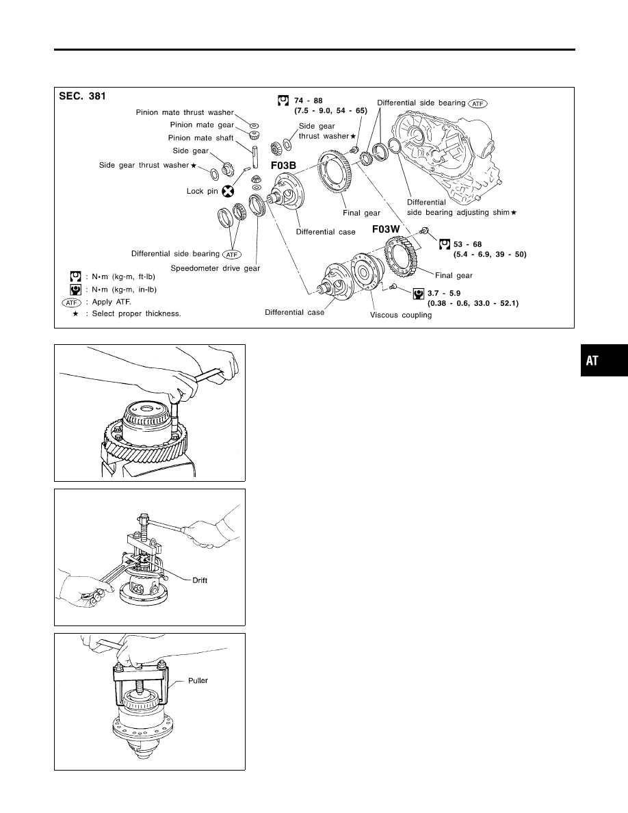
COMPONENTS
NCAT0169
SAT145IC
SMT696B
DISASSEMBLY
NCAT0170
1.
Remove final gear.
SAT312D
SMT697B
2.
Press out differential side bearings.
GI
MA
EM
LC
EC
FE
CL
MT
AX
SU
BR
ST
RS
BT
HA
SC
EL
IDX
REPAIR FOR COMPONENT PARTS
Final Drive
AT-361