Infiniti G20 (P11). Manual - part 92
SAT326D
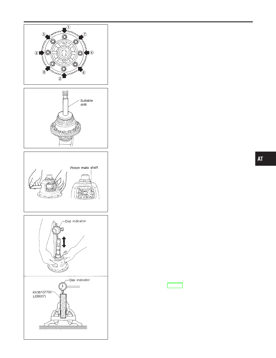
7.
Install final gear and tighten fixing bolts in numerical order.
SMT700B
8.
Press on differential side bearings.
SAT318D
— RE4F03W —
NCAT0172S02
1.
Install side gear and thrust washers in differential case.
2.
Install pinion mate gears and thrust washers in differential case
while rotating them.
I
When inserting, be careful not to damage pinion mate gear
washers.
I
Apply ATF to any parts.
SAT903DA
3.
Measure clearance between side gear and differential case &
viscous coupling with washers using the following procedure:
Differential Case Side
NCAT0172S0201
1)
Set Tool and dial indicator on side gear.
2)
Move side gear up and down to measure dial indicator deflec-
tion.
Clearance between side gear and differential case with
washers:
0.1 - 0.2 mm (0.004 - 0.008 in)
3)
If not within specification adjust clearance by changing thick-
ness of side gear thrust washer.
Side gear thrust washers for differential case side:
Refer to SDS, AT-393.
GI
MA
EM
LC
EC
FE
CL
MT
AX
SU
BR
ST
RS
BT
HA
SC
EL
IDX
REPAIR FOR COMPONENT PARTS
Final Drive (Cont’d)
AT-365