Infiniti FX35 / FX45. Manual - part 746
GW-68
< SERVICE INFORMATION >
REAR WINDOW DEFOGGER
CONSULT-III Function (IPDM E/R)
INFOID:0000000001328007
DATA MONITOR
ACTIVE TEST
Work Flow
INFOID:0000000001328008
1.
Check the symptom and customer's requests.
2.
Understand the outline of system. Refer to
3.
According to the trouble diagnosis chart, repair or replace the cause of the malfunction. Refer to
"Trouble Diagnosis Symptom Chart"
.
4.
Does rear window defogger operate normally? YES: GO TO 5, NO: GO TO 3.
5.
INSPECTION END.
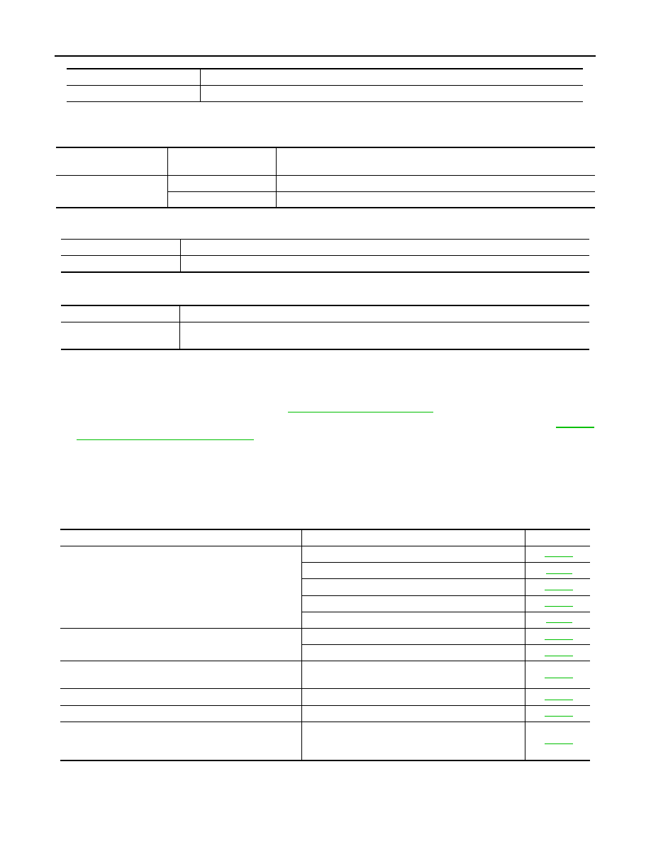
Trouble Diagnosis Symptom Chart
INFOID:0000000001328009
Make sure other systems using the signal of the following systems operate normally.
Test item
Content
REAR DEFOGGER
Gives a drive signal to the rear window defogger relay to activate it.
IPDM E/R diagnostic test
item
Check item diagnostic
test mode
Content
REAR DEFOGGER
Data monitor
Displays the input data of BCM in real time.
Active test
Gives a drive signal to a load to check the operation.
Monitored Item
Description
RR DEF REQ
Indicates [ON/OFF] condition of rear window defogger function by IPDM E/R.
Test Item
Description
REAR DEFOGGER
This test is able to check rear window defogger operation. Rear window defogger operates when “ON”
on CONSULT-III screen is touched.
Symptom
Diagnoses / Service procedure
Refer to page
Rear window defogger and door mirror defogger do not op-
erate.
1.
Check BCM power supply and ground circuit
2. Check IPDM E/R auto active test
3. Check rear window defogger switch circuit
4. Check rear window defogger power supply circuit
5. Replace IPDM E/ R
Rear window defogger does not operate but both of door
mirror defogger operate.
1. Check rear window defogger circuit
2. Check filament
Door mirror defogger does not operated but both of rear
window defogger operate.
Check door mirror defogger power supply circuit
Driver side door mirror defogger does not operate.
Check driver side door mirror defogger circuit
Passenger side door mirror defogger does not operate.
Check passenger side door mirror defogger circuit
Rear window defogger switch does not light, and rear win-
dow defogger is not displayed on the display.
But rear window defogger operates.
Check rear window defogger signal