Infiniti FX35 / FX45. Manual - part 744


  Index      Infiniti     Infiniti FX35 / FX45 (S50) - service repair manual 2008 year


Search            


Content   ..  742  743  744  745   ..


Infiniti FX35 / FX45. Manual - part 744


GW-60

< SERVICE INFORMATION >

REAR WINDOW DEFOGGER

REAR WINDOW DEFOGGER

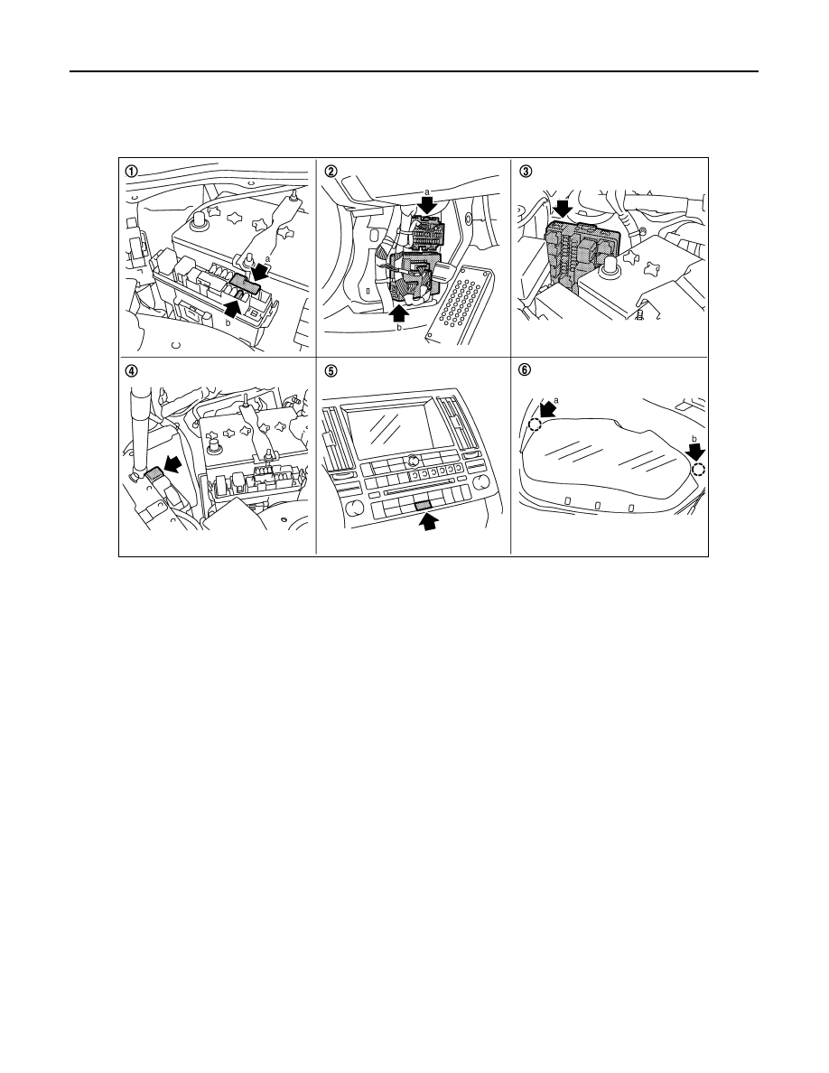
Component Parts and Harness Connector Location

INFOID:0000000001327998

System Description

INFOID:0000000001327999

The rear window defogger system is controlled by BCM (Body Control Module) and IPDM E/R (Intelligent
Power Distribution Module Engine Room). 
The rear window defogger  operates only for approximately 15 minutes. 
Power is at all times supplied
• through 20A fuse [No. 75, located in the IPDM E/R] 
• to rear window defogger relay terminals 3,
• through 20A fuse [No. 80, located in the IPDM E/R] 
• to rear window defogger relay terminals 6,
• through 15A fuse [No. 32, located in the fuse block (J/B)]
• to A/C and AV switch terminal 1,
• through 50A fusible link (letter M, located in the fuse and fusible link box)
• to BCM terminal 55,
• through 15A fuse [No. 22, located in the fuse block (J/B)]
• to BCM terminal 42.
With the ignition switch turned to ON or START position, 
Power is supplied
• through 15A fuse [No. 1, located in the fuse block (J/B)]
• to BCM terminal 38.
• through 10A fuse [No. 12, located in the fuse block]
• to rear window defogger relay terminal 1,
Ground is supplied 
• to BCM terminal 49 and 52

1.

a: Fusible link 50A letter M
b: Fuse 15A No.32

2.

a: Fuse block (J/B) M1, M2, E201
b: BCM M3, M4

3.

IPDM E/R E4, E8, E9

4.

Rear window defogger relay  E13

5.

A/C and AV switch M64
(Rear window defogger switch)

6.

a: Rear window defogger D104
b: Rear window defogger D114

PIIB8568E

REAR WINDOW DEFOGGER

GW-61

< SERVICE INFORMATION >

C

D

E

F

G

H

J

K

L

M

A

B

GW

N

O

P

• through body grounds M35, M45 and M85,
• to A/C and AV switch terminal 5
• through body grounds M35, M45 and M85,
• to IPDM E/R terminals 38 and 60
• through body grounds E21, E50 and E51. 
When rear window defogger switch in A/C and AV switch is turned to ON,  
Ground is supplied 
• to BCM terminal 9
• through A/C and AV switch terminal 16 
• through A/C and AV switch terminal 5 and
• through body grounds M35, M45 and M85.
Then rear window defogger switch is illuminated.
Then BCM recognizes that rear window defogger switch is turned to ON. 
Then it sends rear window defogger switch signals to IPDM E/R, display control unit via DATA LINE (CAN H,
CAN L).
When display control unit receives rear window defogger switch signals, and display on the screen.
When IPDM E/R receives rear window defogger switch signals, 
Ground is supplied
• to rear window defogger relay terminal 2
• through IPDM E/R terminal 52
• through IPDM E/R terminals 38 and 60 and
• through body grounds E21, E50 and E51. 
And then rear window defogger relay is energized. 
When rear window defogger relay is turned ON, signals are transmitted.
• through rear window defogger relay terminals 5 and 7
• to rear window defogger terminal 1
Rear window defogger terminal 2 is grounded through grounds B15 and B45. 
With power and ground supplied, rear window defogger filaments heat and defog the rear window.
When rear window defogger relay is turned to ON, 
Power is supplied
• through rear window defogger relay terminal 7
• through fuse block (J/B) terminal 2C
• through 15A fuse [No. 8, located in the fuse block (J/B)] and
• through fuse block (J/B) terminal 5B
• to door mirror defogger (driver side and passenger side) terminal 4.
Door mirror defogger (driver side and passenger side) terminal 3 is grounded through body grounds M35, M45
and M85.
With power and ground supplied, rear window defogger filaments heat and defog the rear window and door
mirror defogger filaments heat and defog the mirror. 

CAN Communication System Description

INFOID:0000000001328000

CAN (Controller Area Network) is a serial communication line for real time application. It is an on-vehicle mul-
tiplex communication line with high data communication speed and excellent error detection ability. Many elec-
tronic control units are equipped onto a vehicle, and each control unit shares information and links with other
control units during operation (not independent). In CAN communication, control units are connected with 2
communication lines (CAN H line, CAN L line) allowing a high rate of information transmission with less wiring.
Each control unit transmits/receives data but selectively reads required data only.

CAN Communication Unit

INFOID:0000000001328001

Refer to 

LAN-43, "CAN System Specification Chart"

.

GW-62

< SERVICE INFORMATION >

REAR WINDOW DEFOGGER

Schematic

INFOID:0000000001328002

TIWM1684E

REAR WINDOW DEFOGGER

GW-63

< SERVICE INFORMATION >

C

D

E

F

G

H

J

K

L

M

A

B

GW

N

O

P

Wiring Diagram - DEF -

INFOID:0000000001328003

TIWM1685E


Content   ..  742  743  744  745   ..