Infiniti FX35 / FX45. Manual - part 391
DTC P0340, P0345 CMP SENSOR (PHASE)
EC-325
< SERVICE INFORMATION >
[VQ35DE]
C
D
E
F
G
H
I
J
K
L
M
A
EC
N
P
O
3.
If 1st trip DTC is detected, go to
If 1st trip DTC is not detected, go to next step.
4.
Maintaining engine speed at more than 800 rpm for at least 5 seconds.
5.
Check 1st trip DTC.
6.
If 1st trip DTC is detected, go to
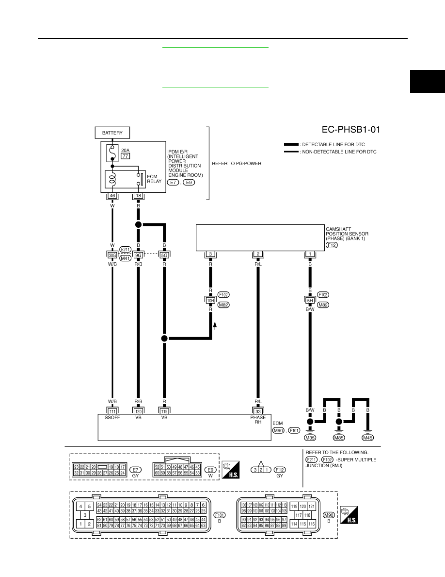
Wiring Diagram
INFOID:0000000001326153
BANK 1
TBWM1388E