Infiniti FX35 / FX45. Manual - part 217
FRONT DOOR LOCK
BL-135
< SERVICE INFORMATION >
C
D
E
F
G
H
J
K
L
M
A
B
BL
N
O
P
FRONT DOOR LOCK
Removal and Installation
INFOID:0000000001327877
REMOVAL
1.
Remove the front door finisher. Refer to
EI-36, "Component Parts Location"
.
2.
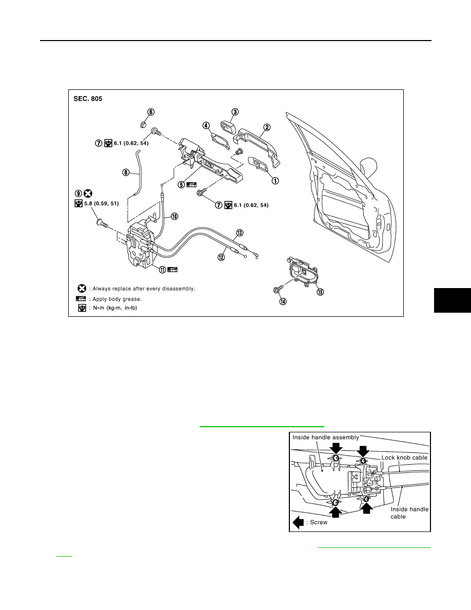
Disconnect the inside handle knob cable and lock knob cable
from the back side of the front door finisher.
3.
Remove the front door glass and front door module assembly. Refer to
4.
Remove door side grommet, and remove door key cylinder assembly (driver side) and outside handle
escutcheon (passenger side) TORX bolt from grommet hole.
CAUTION:
1.
Front gasket
2.
Outside handle
3.
Door key cylinder assembly (Driver
side)
Outside handle escutcheon (Pas-
senger side)
4.
Rear gasket
5.
Outside handle bracket
6.
Grommet
7.
TORX bolt
8.
Key cylinder rod (Driver side only)
9.
TORX bolt
10. Outside handle cable
11.
Door lock assembly
12. Inside handle knob cable
13. Lock knob cable
14. Screw
15. Inside handle
PIIA6025E
PIIA4014E