Infiniti EX35. Manual - part 863
FRONT SUSPENSION MEMBER
FSU-37
< ON-VEHICLE REPAIR >
[AWD]
C
D
F
G
H
I
J
K
L
M
A
B
FSU
N
O
P
FRONT SUSPENSION MEMBER
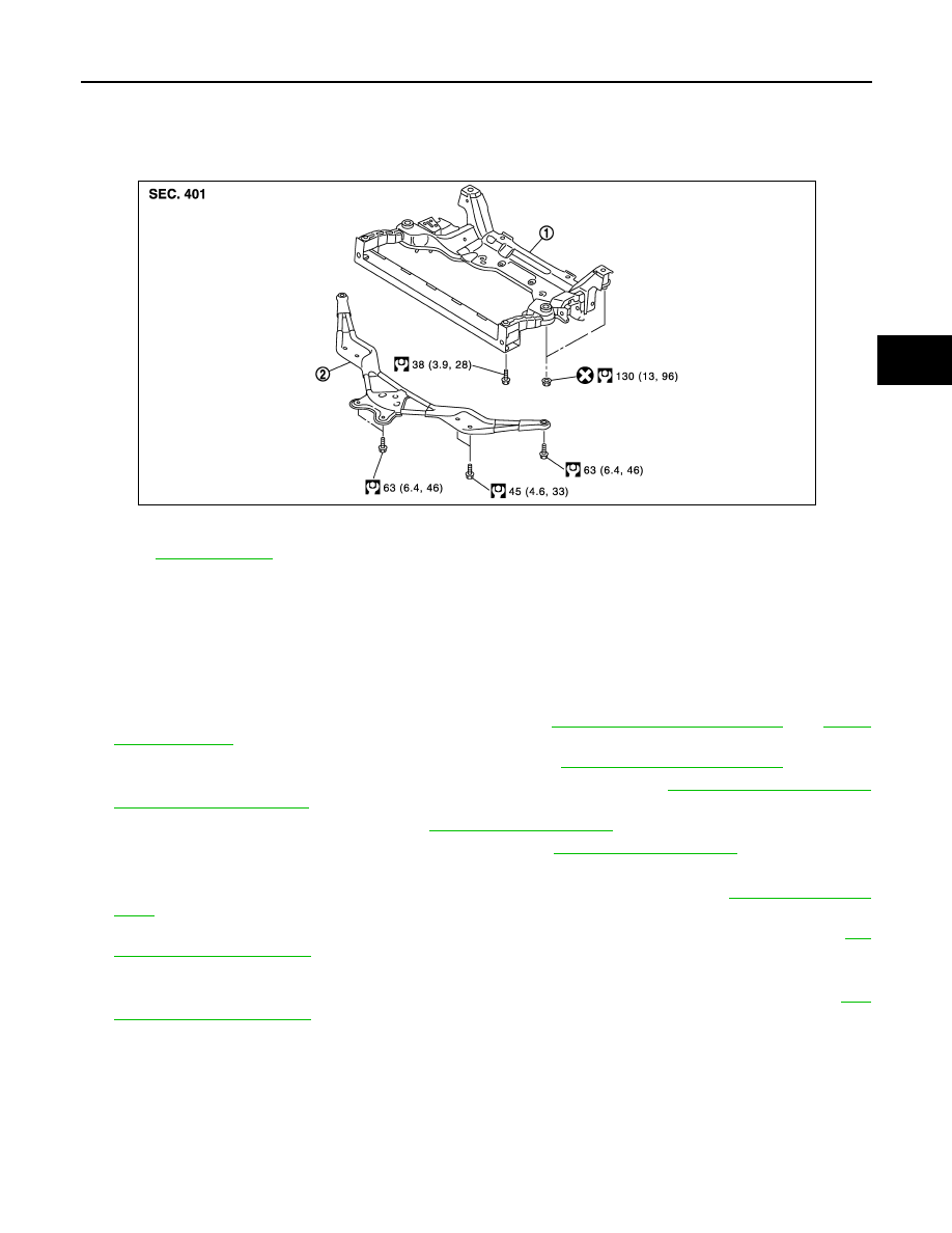
Exploded View
INFOID:0000000003129947
Removal and Installation
INFOID:0000000003129948
REMOVAL
1.
Remove tire with power tool.
2.
Remove under cover with power tool.
3.
Remove front cross bar with power tool.
4.
Separate steering gear assembly and lower joint. Refer to
5.
Remove steering outer socket from steering knuckle. Refer to
.
6.
Remove wheel sensor and sensor harness from steering knuckle. Refer to
.
7.
Remove strut from transverse link. Refer to
.
8.
Remove stabilizer connecting rod and stabilizer bar. Refer to
.
9.
Install engine slinger, and then hoist engine.
10. Remove transverse link from front suspension member with power tool. Refer to
.
11. Remove steering hydraulic piping bracket and steering gear from front suspension member. Refer to
12. Set suitable jack front suspension member.
13. Remove mounting nuts between engine mounting insulator and from suspension member. Refer to
14. Remove mounting bolts and nuts of front suspension member with power tool.
15. Gradually lower jack to remove front suspension assembly from vehicle.
INSTALLATION
Note the following, and install in the reverse order of removal.
• Perform final tightening of bolts and nut at the vehicle installation position (rubber bushing), under unladen
condition with tires on level ground.
1.
Front suspension member
2.
Front cross bar
Refer to
JPEIA0089GB