Infiniti EX35. Manual - part 862
TRANSVERSE LINK
FSU-33
< ON-VEHICLE REPAIR >
[AWD]
C
D
F
G
H
I
J
K
L
M
A
B
FSU
N
O
P
NOTE:
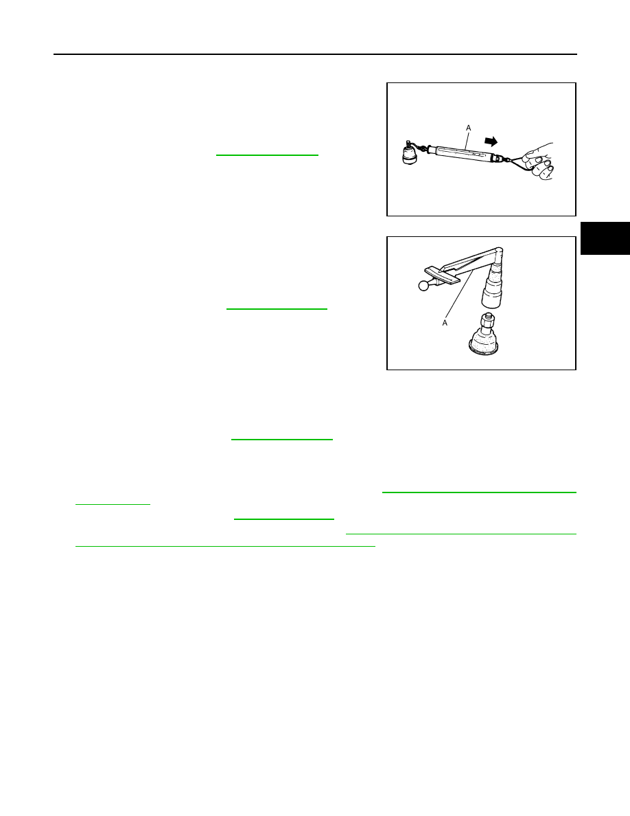
Before measurement, move ball stud at least ten times by hand to check for smooth movement.
• Hook a spring balance (A) at cotter pin mounting hole. Confirm
spring balance measurement value is within specifications when
ball stud begins moving.
- If swing torque exceeds standard range, replace transverse link
assembly.
Rotating Torque Inspection
• Attach mounting nut to ball stud. Make sure that rotating torque is
within specifications with a preload gauge (A) [SST: 3127S000 (J-
25765-A)].
- If rotating torque exceeds standard range, replace transverse link
assembly.
Axial End Play Inspection
• Move tip of ball stud in axial direction to check for looseness.
- If axial end play exceeds standard range, replace transverse link assembly.
INSPECTION AFTER INSTALLATION
1.
Check wheel sensor harness for proper connection. Refer to
BRC-107, "FRONT WHEEL SENSOR :
.
2.
Check wheel alignment. Refer to
3.
Adjust neutral position of steering angle sensor. Refer to
BRC-8, "ADJUSTMENT OF STEERING ANGLE
SENSOR NEUTRAL POSITION : Special Repair Requirement"
.
Standard
Swing toque
JPEIA0005ZZ
Standard
Rotating toque
: Refer to
.
PDIA1258E
Standard
Axial end play
:Refer to
.