Infiniti EX35. Manual - part 860


  Index      Infiniti     Infiniti EX35 - service repair manual 2008 year


Search            


Content   ..  858  859  860  861   ..


Infiniti EX35. Manual - part 860


PREPARATION

FSU-25

< PREPARATION >

[AWD]

C

D

F

G

H

I

J

K

L

M

A

B

FSU

N

O

P

PREPARATION

PREPARATION

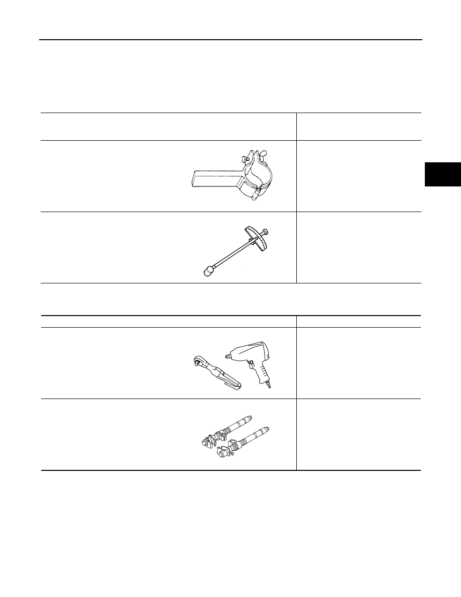
Special Service Tool

INFOID:0000000003129930

The actual shapes of Kent-Moore tools may differ from those of special service tools illustrated here.

Commercial Service Tool

INFOID:0000000003129931

Tool number
(Kent-Moore No.)
Tool name

Description

ST35652000
(

)

Strut attachment

Disassembling and assembling strut

ST3127S000
(J-25765-A)
Preload gauge

Measuring rotating torque of ball joint

ZZA0807D

ZZA0806D

Tool name

Description

Power tool

Loosening bolts and nuts

Spring compressor

Removing and installing coil spring

PBIC0190E

S-NT717

FSU-26

< ON-VEHICLE MAINTENANCE >

[AWD]

FRONT SUSPENSION ASSEMBLY

ON-VEHICLE MAINTENANCE

FRONT SUSPENSION ASSEMBLY

Inspection

INFOID:0000000003129932

MOUNTING INSPECTION

Make sure the mounting conditions (looseness, backlash) of each component and component conditions
(wear, damage) are normal.

BALL JOINT AXIAL END PLAY

1.

Set front wheels in a straight-ahead position.

CAUTION:

Never depress brake pedal when measuring.

2.

Place an iron bar or equivalent between transverse link or upper link and steering knuckle.

3.

Measure axial end play by playing it up and down.

CAUTION:

Be careful not to damage ball joint boot. never damage the installation position by applying exces-
sive force.

Strut

Check for oil leakage, damage. Replace it if necessary.

Standard

Axial end play

: Refer to 

FSU-39, "Ball Joint"

.

WHEEL ALIGNMENT

FSU-27

< ON-VEHICLE MAINTENANCE >

[AWD]

C

D

F

G

H

I

J

K

L

M

A

B

FSU

N

O

P

WHEEL ALIGNMENT

Inspection

INFOID:0000000003129933

DESCRIPTION

CAUTION:

• Camber, caster, kingpin inclination angles cannot be adjusted.
• If camber, caster, or kingpin inclination angle is outside the standard, check front suspension parts

for wear and damage. Replace suspect parts if a malfunction is detected.

• Kingpin inclination angle is reference value, no inspection is required.
• Measure wheel alignment under unladen conditions. 
NOTE:
“Unladen conditions” means that fuel, engine coolant, and lubricant are full. Spare tire, jack, hand tools and
mats are in designated positions.

PRELIMINARY CHECK

Check the following:
• Tires for improper air pressure and wear.
• Road wheels for runout. Refer to 

WT-97, "Inspection"

.

• Wheel bearing axial end play. Refer to 

FAX-14, "Inspection"

.

• Transverse link or upper link ball joint axial end play. Refer to 

FSU-32, "Inspection"

 or 

FSU-34, "Inspection"

.

• Strut operation.
• Each mounting part of axle and suspension for looseness and deformation.
• Each of suspension member, strut, upper link and transverse link for cracks, deformation and other damage.
• Vehicle height (posture).

GENERAL INFORMATION AND RECOMMENDATIONS

• A four-wheel thrust alignment should be performed.
- This type of alignment is recommended for any NISSAN/INFINITI vehicle.
- The four-wheel “thrust” process helps ensure that the vehicle is properly aligned and the steering wheel is

centered.

- The alignment rack itself should be capable of accepting any NISSAN/INFINITI vehicle.
- The rack should be checked to ensure that it is level.
• Make sure the machine is properly calibrated.
- Your alignment equipment should be regularly calibrated in order to give correct information.
- Check with the manufacturer of your specific equipment for their recommended Service/Calibration Sched-

ule.

 ALIGNMENT PROCESS

IMPORTANT:
Use only the alignment specifications listed in this Service Manual.
• When displaying the alignment settings, many alignment machines use “indicators”: (Green/red, plus or

minus, Go/No Go). Do not use these indicators.

- The alignment specifications programmed into your machine that operate these indicators may not be cor-

rect.

- This may result in an ERROR.
• Some newer alignment machines are equipped with an optional “Rolling Compensation” method to “com-

pensate” the sensors (alignment targets or head units). Never use this “Rolling Compensation” method.

- Use the “Jacking Compensation Method”. After installing the alignment targets or head units, raise the vehi-

cle and rotate the wheels 1/2 turn both ways.

- See Instructions in the alignment machine you're using for more information on this.

FSU-28

< ON-VEHICLE REPAIR >

[AWD]

FRONT COIL SPRING AND STRUT

ON-VEHICLE REPAIR

FRONT COIL SPRING AND STRUT

Exploded View

INFOID:0000000003129934

Removal and Installation

INFOID:0000000003129935

REMOVAL

1.

Remove tires with power tool.

2.

Remove wheel sensor and harness connector from strut. Refer to 

BRC-107, "FRONT WHEEL SENSOR :

Exploded View"

.

CAUTION:

Never pull on wheel sensor harness.

3.

Remove brake hose bracket. Refer to 

BR-20, "FRONT : Exploded View"

.

4.

Remove stabilizer connecting rod with power tool. Refer to 

FSU-36, "Exploded View"

.

5.

Remove strut from transverse link with power tool.

6.

Separate upper link from steering knuckle. Refer to 

FAX-16, "Exploded View"

.

7.

Remove strut assembly.
NOTE:
If removing strut is difficult, loosen upper link mounting bolts (vehicle side).

INSTALLATION

Note the following, and install in the reverse order of removal.
• Never tap on the ball joint cap of the stabilizer connecting rod with a hammer or a similar item when inserting

the stabilizer connecting rod into the transverse link.

• Perform final tightening of bolts and nuts at the strut lower side (rubber bushing), under unladen conditions

with tires on level ground.

Disassembly and Assembly

INFOID:0000000003129936

DISASSEMBLY

CAUTION:

Never damage strut piston rod when removing components from strut.

1.

Strut 

2.

Rubber seat

3.

Coil spring

4.

Mounting seal

5.

Strut mounting bracket

6.

Bound bumper

Refer to 

GI-4, "Components"

 for symbols in the figure.

JPEIA0086GB


Content   ..  858  859  860  861   ..