Infiniti EX35. Manual - part 858
FRONT STABILIZER
FSU-17
< ON-VEHICLE REPAIR >
[2WD]
C
D
F
G
H
I
J
K
L
M
A
B
FSU
N
O
P
FRONT STABILIZER
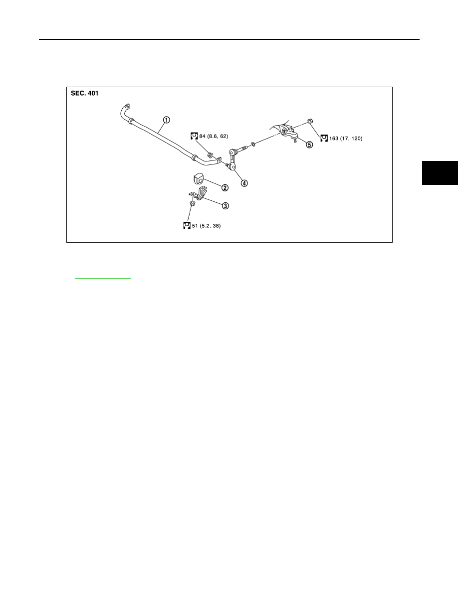
Exploded View
INFOID:0000000003129913
Removal and Installation
INFOID:0000000003129914
REMOVAL
1.
Remove tires with power tool.
2.
Remove under cover with power tool.
3.
Remove stabilizer connecting rod with power tool.
CAUTION:
Apply a matching mark to identify the installation position.
4.
Remove stabilizer clamp and stabilizer bushing.
5.
Remove stabilizer bar.
INSTALLATION
Note the following, and install in the reverse order of removal.
• Check the matching mark when installing.
• Tighten the mounting nut to the specified torque while holding a hexagonal part of stabilizer connecting rod
side.
Inspection
INFOID:0000000003129915
INSPECTION AFTER REMOVAL
Check stabilizer bar, stabilizer connecting rod, stabilizer bushing and stabilizer clamp for deformation, cracks
or damage. Replace it if necessary.
1.
Stabilizer bar
2.
Stabilizer bushing
3.
Stabilizer clamp
4.
Stabilizer connecting rod
5.
Transverse link
Refer to
JPEIA0084GB