Infiniti EX35. Manual - part 293


  Index      Infiniti     Infiniti EX35 - service repair manual 2008 year


Search            


Content   ..  291  292  293  294   ..


Infiniti EX35. Manual - part 293


BCS

DIAGNOSIS SYSTEM (BCM)

BCS-19

< FUNCTION DIAGNOSIS >

C

D

E

F

G

H

I

J

K

L

B

A

O

P

N

DATA MONITOR

ACTIVE TEST

INT LAMP

INT LAMP : CONSULT-III Function (BCM - INT LAMP)

INFOID:0000000003743943

WORK SUPPORT

Test item

Diagnosis mode

Description

BUZZER

Data Monitor

Displays BCM input data in real time.

Active Test

Operation of electrical loads can be checked by sending driving signal to them.

Display item

[Unit]

Description

VEH SPEED 1
[Km/h]

Value of vehicle speed signal received from ABS actuator and electric unit (control unit) with CAN 
communication line.

PUSH SW
[On/Off]

Status of push button ignition switch judged by BCM.

UNLK SEN-DR
[On/Off]

Status of unlock sensor judged by BCM.

KEY SW-SLOT
[On/Off]

Status of key slot judged by BCM.

TAIL LAMP SW
[On/Off]

Status of each switch judged by BCM using the combination switch readout function.

FR FOG SW
[On/Off]

Status of front fog lamp switch judged by BCM.

DOOR SW-DR
[On/Off]

Status of driver side door switch judged by BCM.

Display item

[Unit]

Description

IGN KEY WARN ALM

The key warning chime operation can be checked by operating the relevant function (On/Off).

SEAT BELT WARN TEST

The seat belt warning chime operation can be checked by operating the relevant function (On/Off).

ID REGIST WARNING

The ID regist warning chime operation can be checked by operating the relevant function (On/Off).

LIGHT WARN ALM

The light warning chime operation can be checked by operating the relevant function (On/Off).
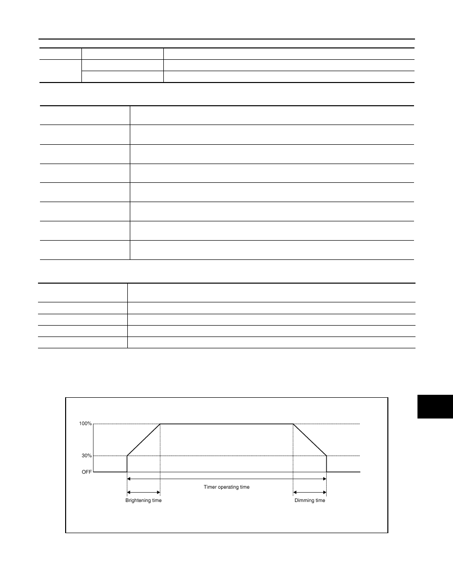
JPLIA0093GB

BCS-20

< FUNCTION DIAGNOSIS >

DIAGNOSIS SYSTEM (BCM)

*: Initial setting

DATA MONITOR

Service item

Setting item

Setting

SET I/L D-UNLCK INTCON

ON*

With the interior room lamp timer function

OFF

Without the interior room lamp timer function

ROOM LAMP TIMER SET

MODE 2

7.5 sec.

Sets the interior room lamp ON time. (Timer operating time)

MODE 3*

15 sec.

MODE 4

30 sec.

ROOM LAMP ON TIME SET

MODE 1

0.5 sec.

Sets the interior room lamp gradual brightening time.

MODE 2*

1 sec.

MODE 3

2 sec.

MODE 4

3 sec.

MODE 5

0 sec.

ROOM LAMP OFF TIME SET

MODE 1

0.5 sec.

Sets the interior room lamp gradual dimming time.

MODE 2

1 sec.

MODE 3

2 sec.

MODE 4*

3 sec.

MODE 5

0 sec.

R LAMP TIMER LOGIC SET

MODE 1*

Interior room lamp timer activates with synchronizing all doors.

MODE 2

Interior room lamp timer activates with synchronizing the driver door 
only.

Monitor item

[Unit]

Description

REQ SW-DR
[On/Off]

The switch status input from request switch (driver side)

REQ SW-AS
[On/Off]

The switch status input from request switch (passenger side)

PUSH SW
[On/Off]

The switch status input from push-button ignition switch

KEY SW-SLOT
[On/Off]

Key switch status input from key slot

DOOR SW-DR
[On/Off]

The switch status input from front door switch (driver side)

DOOR SW-AS
[On/Off]

The switch status input from front door switch (passenger side)

DOOR SW-RR
[On/Off]

The switch status input from rear door switch RH

DOOR SW- RL
[On/Off]

The switch status input from rear door switch LH

DOOR SW-BK
[On/Off]

NOTE:
The item is indicated, but not monitored.

CDL LOCK SW
[On/Off]

Lock switch status received from central door lock switch by power window switch se-
rial link

CDL UNLOCK SW
[On/Off]

Unlock switch status received from central door lock switch by power window switch 
serial link

KEY CYL LK-SW
[On/Off]

Lock switch status received from key cylinder switch by power window switch serial 
link

KEY CYL UN-SW
[On/Off]

Unlock switch status received from key cylinder switch by power window switch serial 
link

BCS

DIAGNOSIS SYSTEM (BCM)

BCS-21

< FUNCTION DIAGNOSIS >

C

D

E

F

G

H

I

J

K

L

B

A

O

P

N

ACTIVE TEST

HEADLAMP

HEADLAMP : CONSULT-III Function (BCM - HEAD LAMP)

INFOID:0000000003743945

WORK SUPPORT

*: Initial setting

DATA MONITOR

TRNK/HAT MNTR
[On/Off]

The switch status input from trunk room lamp switch

RKE-LOCK
[On/Off]

Lock signal status received from remote keyless entry receiver

RKE-UNLOCK
[On/Off]

Unlock signal status received from remote keyless entry receiver

Monitor item

[Unit]

Description

Test item

Operation

Description

INT LAMP

On

Outputs the interior room lamp control signal to turn map lamp and personal lamp ON 
(Map lamp switch is in DOOR position).

Off

Stops the interior room lamp control signal to turn map lamp and personal lamp OFF.

STEP LAMP TEST

On

Outputs the step lamp control signal to turn step lamp ON.

Off

Stops the step lamp control signal to turn step lamp OFF.

LUGGAGE LAMP TEST

On

Outputs the trunk room lamp control signal to turn step lamp ON.

Off

Stops the trunk room lamp control signal to turn step lamp ON.

Service item

Setting item

Setting

BATTERY SAVER SET

On*

With the exterior lamp battery saver function

Off

Without the exterior lamp battery saver function

ILL DELAY SET

MODE 1*

45 sec.

Sets delay timer function timer operation time.
(All doors closed)

MODE 2

Without the func-
tion

MODE 3

30 sec.

MODE 4

60 sec.

MODE 5

90 sec.

MODE 6

120 sec.

MODE 7

150 sec.

MODE 8

180 sec.

CUSTOM A/LIGHT SET-
TING

MODE 1*

Normal

MODE 2

More sensitive setting than normal setting (Turns ON earlier than normal operation.)

MODE 3

More sensitive setting than MODE 2 (Turns ON earlier than MODE 2.)

MODE 4

Less sensitive setting than normal setting (Turns ON later than normal operation.)

Monitor item

[Unit]

Description

PUSH SW
[On/Off]

The switch status input from push-button ignition switch

ENGINE STATE
[Stop/Stall/Crank/Run]

The engine status received from ECM with CAN communication

BCS-22

< FUNCTION DIAGNOSIS >

DIAGNOSIS SYSTEM (BCM)

ACTIVE TEST

VEH SPEED 1
[km/h]

The value of the vehicle speed received from unified meter and A/C amp. with CAN 
communication

KEY SW-SLOT
[On/Off]

Key switch status input from key slot

TURN SIGNAL R
[On/Off]

Each switch status that BCM judges from the combination switch reading function

TURN SIGNAL L
[On/Off]

TAIL LAMP SW
[On/Off]

HI BEAM SW
[On/Off]

HEAD LAMP SW1
[On/Off]

HEAD LAMP SW2
[On/Off]

PASSING SW
[On/Off]

AUTO LIGHT SW
[On/Off]

FR FOG SW
[On/Off]

RR FOG SW
[On/Off]

NOTE:
The item is indicated, but not monitored.

DOOR SW-DR
[On/Off]

The switch status input from front door switch (driver side)

DOOR SW-AS
[On/Off]

The switch status input from front door switch (passenger side)

DOOR SW-RR
[On/Off]

The switch status input from rear door switch RH

DOOR SW- RL
[On/Off]

The switch status input from rear door switch LH

DOOR SW-BK
[On/Off]

NOTE:
The item is indicated, but not monitored.

OPTICAL SENSOR
[V]

The value of exterior brightness voltage input from the optical sensor 

Monitor item

[Unit]

Description

Test item

Operation

Description

TAIL LAMP

On

Transmits the position light request signal to IPDM E/R with CAN com-
munication to turn the tail lamp ON.

Off

Stops the position light request signal transmission.

HEAD LAMP

Hi

Transmits the high beam request signal with CAN communication to turn 
the headlamp (HI).

Low

Transmits the low beam request signal with CAN communication to turn 
the headlamp (LO).

Off

Stops the high & low beam request signal transmission.

FR FOG LAMP

On

Transmits the front fog light request signal to IPDM E/R with CAN com-
munication to turn the front fog lamp ON.

Off

Stops the front fog light request signal transmission.


Content   ..  291  292  293  294   ..