Infiniti EX35. Manual - part 291


  Index      Infiniti     Infiniti EX35 - service repair manual 2008 year


Search            


Content   ..  289  290  291  292   ..


Infiniti EX35. Manual - part 291


BCS

COMBINATION SWITCH READING SYSTEM

BCS-11

< FUNCTION DIAGNOSIS >

C

D

E

F

G

H

I

J

K

L

B

A

O

P

N

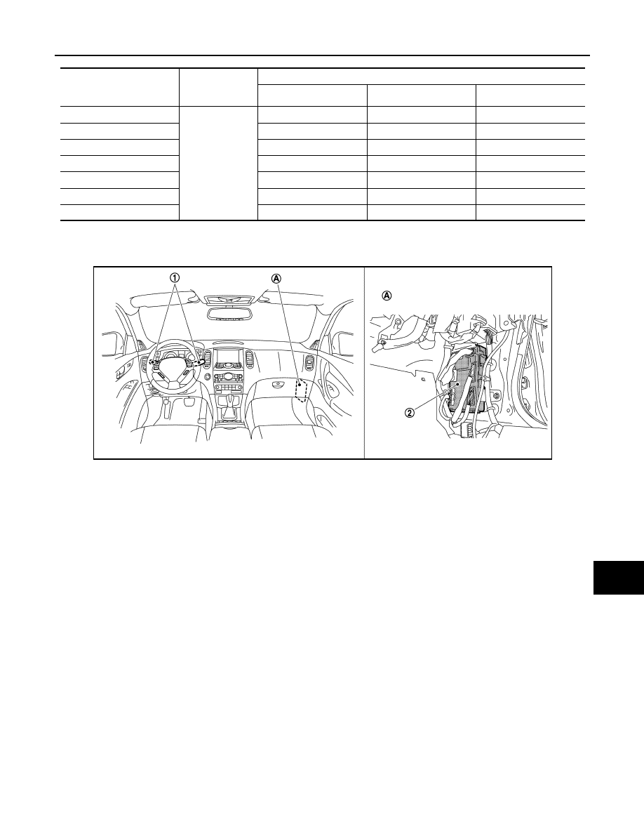
Component Parts Location

INFOID:0000000003528882

Wiper intermittent

dial position

Intermittent

operation delay

interval

INT VOLUME switch ON/OFF status  

INT VOLUME 1 switch

INT VOLUME 2 switch

INT VOLUME 3 switch

1

Short

Long

ON

ON

ON

2

ON

ON

OFF

3

ON

OFF

OFF

4

OFF

OFF

OFF

5

OFF

OFF

ON

6

OFF

ON

ON

7

OFF

ON

OFF

1.

Combination switch

2.

BCM

A.

Dash side lower (Passenger side)

JPMIA0939ZZ

BCS-12

< FUNCTION DIAGNOSIS >

SIGNAL BUFFER SYSTEM

SIGNAL BUFFER SYSTEM

System Diagram

INFOID:0000000003137909

System Description

INFOID:0000000003137910

OUTLINE

BCM has the signal transmission function that outputs/transmits each input/received signal to each unit.

Signal transmission function list

JPMIA1013GB

Signal name

Input

Output

Description

• Ignition switch ON signal
• Ignition switch signal

Push-button ignition switch 
(push switch)

• IPDM E/R (CAN)
• Driver seat control unit (CAN)

Inputs the push-button ignition 
switch (push switch) signal and 
transmits the ignition switch sta-
tus judged with BCM via CAN 
communication.

Door switch signal

Any door switch

• Combination meter (via uni-

fied meter and A/C amp.) 
(CAN)

• IPDM E/R (CAN)
• Driver seat control unit (CAN)
• AV control unit (CAN)

Inputs the door switch signal 
and transmits it via CAN com-
munication.

Oil pressure switch signal

IPDM E/R (CAN)

Combination meter (via unified 
meter and A/C amp.) (CAN)

Transmits the received oil pres-
sure switch signal via CAN 
communication.

Stop lamp switch signal

• Stop lamp switch
• ICC brake hold relay (With 

ICC)

TCM (CAN)

Inputs the stop lamp switch sig-
nal or ICC brake hold relay (with 
ICC) signal, and transmits it via 
CAN communication.

BCS

POWER CONSUMPTION CONTROL SYSTEM

BCS-13

< FUNCTION DIAGNOSIS >

C

D

E

F

G

H

I

J

K

L

B

A

O

P

N

POWER CONSUMPTION CONTROL SYSTEM

System Diagram

INFOID:0000000003137911

System Description

INFOID:0000000003137912

OUTLINE

• BCM incorporates a power saving control function that reduces the power consumption according to the

vehicle status. 

• BCM switches the status (control mode) by itself with the power saving control function. It performs the sleep

request to each unit [IPDM E/R, combination meter (unified meter and A/C amp.) and driver seat control unit]
that operates with the ignition switch OFF.

Normal mode (wake-up)

- CAN communication is normally performed with other units
- Each control with BCM is operating properly

CAN communication sleep mode (CAN sleep)

- CAN transmission is stopped
- Control with BCM only is operating

Low power consumption mode (BCM sleep)

- Low power consumption control is active
- CAN transmission is stopped

LOW POWER CONSUMPTION CONTROL WITH BCM

BCM reduces the power consumption with the following operation in the low power consumption mode.
• The reading interval of the each switches changes from 10 ms interval to 60 ms interval.

Sleep mode activation

• BCM receives the sleep-ready signal (ready) from IPDM E/R and unified meter and A/C amp. via CAN com-

munication.

• BCM transmits the sleep wake up signal (sleep) to each unit when all of the CAN sleep conditions are ful-

filled.

• Each unit stops the transmission of CAN communication with the sleep wake up signal. BCM is in CAN com-

munication sleep mode.

• BCM is in the low power consumption mode and perform the low power consumption control when all of the

BCM sleep conditions are fulfilled with CAN sleep condition.

JPMIA0069GB

BCS-14

< FUNCTION DIAGNOSIS >

POWER CONSUMPTION CONTROL SYSTEM

Sleep condition

Wake-up operation

• BCM changes from the low power consumption mode to the CAN communication sleep mode when the any

of the BCM wake-up conditions is fulfilled. Only the control with BCM is activated.

• BCM transmits the sleep wake up signal (wake up) to each unit when any of the CAN wake-up conditions is

fulfilled. It changes from the low power consumption mode or the CAN communication sleep mode to the
normal mode.

• Each unit starts the transmission of CAN communication with the sleep wake up signal. In addition, the uni-

fied meter and A/C amp. transmits the wake up signal to BCM via CAN communication to report the CAN
communication start.

Wake-up condition

CAN sleep condition

BCM sleep condition

• Receiving the sleep-ready signal (ready) from all units
• Ignition switch: OFF
• Vehicle security system and panic alarm: Not operation
• Warning chime: Not operation
• Intelligent Key system buzzer: Not operation
• Stop lamp switch: OFF
• ICC brake hold relay (with ICC): ON
• Key slot (card switch) status: No change
• Turn signal indicator lamp: Not operation
• Exterior  lamp:  OFF
• Door lock status: No change
• CONSULT-III communication status: Not communication
• Meter display signal: Non-transmission
• Door switch status: No change
• Rear window defogger: OFF

• Interior room lamp battery saver: Time out
• RAP system: OFF
• Power window switch communication: No transmission
• Push-button ignition switch illumination: OFF
• Infiniti Vehicle Immobilizer System (IVIS) - NATS: Not operation
• Remote keyless entry receiver communication status: No com-

munication

• Tire pressure monitor system (TPMS) - AIR PRESSURE MON-

ITOR: Stop

• LOCK indicator lamp: Not operation
• ACC indicator lamp: Not operation
• ON indicator lamp: Not operation

BCM wake-up condition

CAN wake-up condition

• Power window switch communication: Receiving
• Remote keyless entry receiver: Receiving
• Front door lock assembly driver side (unlock sensor):

OFF 

 ON, ON 

 OFF

• Receiving the sleep-ready signal (Not-ready) from any units
• Key slot (key switch): OFF 

 ON, ON 

 OFF

• Push-button ignition switch (push switch): OFF

 ON

• Hazard switch: OFF 

 ON

• PASSING switch: OFF 

 ON, ON 

 OFF

• TAIL LAMP switch: OFF 

 ON

• Driver door switch: OFF 

 ON, ON 

 OFF

• Passenger door switch: OFF 

 ON, ON 

 OFF

• Rear RH door switch: OFF 

 ON, ON 

 OFF

• Rear LH door switch: OFF 

 ON, ON 

 OFF

• Back door switch: OFF 

 ON, ON 

 OFF

• Driver door request switch: OFF 

 ON

• Passenger door request switch: OFF 

 ON

• Back door opener request switch: OFF 

 ON

• Stop lamp switch: ON
• ICC brake hold relay (with ICC): ON


Content   ..  289  290  291  292   ..