Infiniti EX35. Manual - part 292


  Index      Infiniti     Infiniti EX35 - service repair manual 2008 year


Search            


Content   ..  290  291  292  293   ..


Infiniti EX35. Manual - part 292


BCS

POWER CONSUMPTION CONTROL SYSTEM

BCS-15

< FUNCTION DIAGNOSIS >

C

D

E

F

G

H

I

J

K

L

B

A

O

P

N

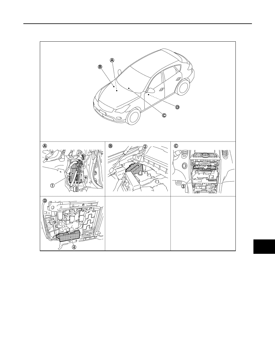
Component Parts Location

INFOID:0000000003137913

1.

BCM

2.

IPDM E/R

3.

Unified meter and A/C amp.

4.

Driver seat control unit

A.

Dash side lower (passenger side)

B.

Engine room dash panel (RH)

C.

Behind cluster lid C

D.

Backside of the seat cushion (driver 
seat)

JPMIA0940ZZ

BCS-16

< FUNCTION DIAGNOSIS >

DIAGNOSIS SYSTEM (BCM)

DIAGNOSIS SYSTEM (BCM)

COMMON ITEM

COMMON ITEM : CONSULT-III Function (BCM - COMMON ITEM)

INFOID:0000000003534209

APPLICATION ITEM

CONSULT-III performs the following functions via CAN communication with BCM.

SYSTEM APPLICATION

BCM can perform the following functions for each system.
NOTE:
It can perform the diagnosis modes except the following for all sub system selection items.

×

: Applicable item

NOTE:

*: This item is displayed, but is not used. 

FREEZE FRAME DATA (FFD) AND IGN COUNTER

Freeze Frame Data

Diagnosis mode

Function Description

Work Support

Changes the setting for each system function.

Self Diagnostic Result

Displays the diagnosis results judged by BCM.

CAN Diag Support Monitor

Monitors the reception status of CAN communication viewed from BCM. Refer to CONSULT-III opera-
tion manual.

Data Monitor

The BCM input/output signals are displayed.

Active Test

The signals used to activate each device are forcibly supplied from BCM.

Ecu Identification

The BCM part number is displayed.

Configuration

• Read and save the vehicle specification.
• Write the vehicle specification when replacing BCM.

System

Sub system selection item

Diagnosis mode

Work Support

Data Monitor

Active Test

Door lock

DOOR LOCK

×

×

×

Rear window defogger

REAR DEFOGGER

×

×

Warning chime

BUZZER

×

×

Interior room lamp timer

INT LAMP

×

×

×

Exterior lamp

HEAD LAMP

×

×

×

Wiper and washer

WIPER

×

×

Turn signal and hazard warning lamps

FLASHER

×

×

×

AIR CONDITONER*

• Intelligent Key system
• Engine start system

INTELLIGENT KEY

×

×

×

Combination switch

COMB SW

×

Body control system

BCM

×

IVIS - NATS

IMMU

×

×

Interior room lamp battery saver

BATTERY SAVER

×

×

×

TRUNK*

×

×

Vehicle security system

THEFT ALM

×

×

×

RAP system

RETAINED PWR

×

Signal buffer system

SIGNAL BUFFER

×

×

TPMS

TPMS (AIR PRESSURE MONITOR)

×

×

×

BCS

DIAGNOSIS SYSTEM (BCM)

BCS-17

< FUNCTION DIAGNOSIS >

C

D

E

F

G

H

I

J

K

L

B

A

O

P

N

The BCM records the following condition at the moment a particular DTC is detected.
• Vehicle Speed
• Odd Trip Meter
• Vehicle Condition (BCM detected condition)

IGN Counter

IGN counter indicates the number of times that ignition switch is turned ON after DTC is detected.
• The number is 0 when a malfunction is detected now.
• The number increases like 1 

 2 

 3...38 

 39 after returning to the normal condition whenever ignition

switch OFF 

 ON.

• The number is fixed to 39 until the self-diagnosis results are erased if it is over 39.

DOOR LOCK

DOOR LOCK : CONSULT-III Function (BCM - DOOR LOCK)

INFOID:0000000003743935

BCM CONSULT-III FUNCTION

CONSULT-III performs the following functions via CAN communication with BCM.

WORK SUPPORT

CONSULT screen terms

Description

SLEEP>LOCK

While turning BCM status from low power consumption mode to normal mode (Power supply 
position is “LOCK”)

SLEEP>OFF

While turning BCM status from low power consumption mode to normal mode (Power supply 
position is “OFF”.)

LOCK>ACC

While turning power supply position from “LOCK” to “ACC”

ACC>ON

While turning power supply position from “ACC” to “IGN”

RUN>ACC

While turning power supply position from “RUN” to “ACC” (Vehicle is stopping and selector 
lever is except P position.)

CRANK>RUN

While turning power supply position from “CRANKING” to “RUN” (From cranking up the en-
gine to run it)

RUN>URGENT

While turning power supply position from “RUN“ to “ACC” (Emergency stop operation)

ACC>OFF

While turning power supply position from “ACC” to “OFF”

OFF>LOCK

While turning power supply position from “OFF” to “LOCK”

OFF>ACC

While turning power supply position from “OFF” to “ACC”

ON>CRANK

While turning power supply position from “IGN” to “CRANKING”

OFF>SLEEP

While turning BCM status from normal mode (Power supply position is “OFF”.) to low power 
consumption mode

LOCK>SLEEP

While turning BCM status from normal mode (Power supply position is “LOCK”.) to low pow-
er consumption mode

LOCK

Power supply position is “LOCK” (Ignition switch OFF with steering is locked.)

OFF

Power supply position is “OFF” (Ignition switch OFF with steering is unlocked.)

ACC

Power supply position is “ACC” (Ignition switch ACC)

ON

Power supply position is “IGN” (Ignition switch ON with engine stopped)

ENGINE RUN

Power supply position is “RUN” (Ignition switch ON with engine running)

CRANKING

Power supply position is “CRANKING” (At engine cranking)

Diagnosis mode

Function Description

WORK SUPPORT

Changes the setting for each system function.

DATA MONITOR

The BCM input/output signals are displayed.

ACTIVE TEST

The signals used to activate each device are forcibly supplied from BCM.

BCS-18

< FUNCTION DIAGNOSIS >

DIAGNOSIS SYSTEM (BCM)

DATA MONITOR

ACTIVE TEST

REAR WINDOW DEFOGGER

REAR WINDOW DEFOGGER : CONSULT-III Function (BCM - REAR DEFOGGER)

INFOID:0000000003743948

Data monitor

ACTIVE TEST

BUZZER

BUZZER : CONSULT-III Function (BCM - BUZZER)

INFOID:0000000003743950

CONSULT-III APPLICATION ITEMS

Monitor item

Description

DOOR LOCK-UNLOCK SET

Selective unlock function mode can be changed to operate (WITH) or not operate (WITHOUT) with 
this mode.

Monitor Item

Contents

REQ SW-DR

Indicated [ON/OFF] condition of door request switch (driver side).

REQ SW-AS

Indicated [ON/OFF] condition of door request switch (passenger side).

REQ SW-BD/TR

Indicated [ON/OFF] condition of back door request switch. 

DOOR SW-DR

Indicated [ON/OFF] condition of front door switch (driver side).

DOOR SW-AS

Indicated [ON/OFF] condition of front door switch (passenger side).

DOOR SW-RR

Indicated [ON/OFF] condition of rear door switch RH.

DOOR SW-RL

Indicated [ON/OFF] condition of rear door switch LH.

DOOR SW-BK

Indicated [ON/OFF] condition of back door switch.

CDL LOCK SW

Indicated [ON/OFF] condition of lock signal from door lock unlock switch.

CDL UNLOCK SW

Indicated [ON/OFF] condition of unlock signal from door lock unlock switch.

KEY CYL LK-SW

Indicated [ON/OFF] condition of lock signal from door key cylinder.

KEY CYL UN-SW

Indicated [ON/OFF] condition of unlock signal from door key cylinder.

Test item

Description

DOOR LOCK

This test is able to check door lock/unlock operation.
• The all door lock actuators are locked when “ALL LCK” on CONSULT-III screen is touched.
• The all door lock actuators are unlocked when “ALL UNLK” on CONSULT-III screen is touched.
• The door lock actuator (driver side) is unlocked when “DR UNLK” on CONSULT-III screen is 

touched.

• The door lock actuator (passenger side) is unlocked when “AS UNLK” on CONSULT- III screen 

is touched.

• The door lock actuator (rear LH and RH) is unlocked when “OTR ULK” on CONSULT-III screen 

is touched.

Monitor Item

Description

REAR DEF SW

This is displayed even when it is not equipped.

PUSH SW

Indicates [ON/OFF] condition of push switch.

Test Item

Description

REAR DEFOGGER

This test is able to check rear window defogger operation. Rear window defogger operates when 
“ON” on CONSULT-III screen is touched.


Content   ..  290  291  292  293   ..