Hyundai Matrix (2007 year). Instruction - part 21

CONTROLS AND EQUIPMENT
1
ASHTRAY
DRINK HOLDER
61
B430A01FC-GAT
B450A02FC-EAT
B450B02FC-EAT
Front Drink Holder
Rear Drink Holder
(Not all models)
(Not all models)
Driver's
Passenger's
HFC2056-D
The front ashtray may be opened by
pulling it up by its top edge. To remove
HFC2097-D
HFC2098
the ashtray to empty or clean it, pull the
The front drink holder is used for holding
The rear drink holder is located on the
cover up all the way out. The ashtray
cups.
rear main console for holding cups.
light will only illuminate when the exter-
To use the passenger's drink holder,
The rear drink holder can be used by
nal lights are on.
push the drink holder and pull it entirely.
pushing the knob on the rear main
console downward and then releasing
it.
!
CAUTION:
Place the drink holder in its original
position whilst not in use.
fcuk-1.p65
61
12/27/2006, 10:12 AM

1 CONTROLS AND EQUIPMENT
PARKING BRAKE
62
SB380A2-E
In addition it is recommended that
when parking the vehicle on a gradi-
!
WARNING:
ent, the shift lever should be posi-
o Use caution when using the drink
tioned in the appropriate low gear on
holders. A spilled beverage that is
manual transmission vehicles or in
very hot can injure you or your
the Park position on automatic trans-
passengers. Spilled liquids can
mission vehicles.
damage interior trim and electri-
o
To release the parking brake, first
cal components.
apply the foot brake and pull up the
o Do not place objects other than
parking brake lever slightly. Sec-
cups or drinks in the drink holder.
ondly, depress the release button
Such objects can be thrown out in
and lower the parking brake lever
B530A01FC-D
the event of a sudden stop or an
whilst holding the button.
accident, possibly injuring the pas-
The parking brake must always be set
sengers in the vehicle.
when the vehicle is to be left unattended.
When the parking brake is applied, and
the ignition key is at the "ON" position,
the parking brake warning lamp will be
illuminated. Before driving the vehicle,
the parking brake must be fully released
and the warning lamp extinguished.
o To engage the parking brake, first
apply the foot brake and then without
pressing the release button in, pull the
parking brake lever up as far as pos-
sible.
fcuk-1.p65
62
12/27/2006, 10:12 AM

CONTROLS AND EQUIPMENT
1
REAR SEAT ARM REST
SUNROOF
63
B611A02FC-EAT
SB330A3-E
(Not all models)
(Not all models)
!
WARNING:
Never install or remove the sunshade
whilst driving.
B610A01FC
B470A01FC
This arm rest is located in the centre of
The electrically operated sunroof may
the rear seat back with box.
be used only whilst the ignition switch is
The drink holder in the box can be used
at the "ON" position. The sunroof is
by opening the lid of the arm rest.
equipped with a sunshade which may
HFC2021
be used whilst the sunroof is at the
closed position to obscure incoming
To open the sunroof, depress and hold
light.
the button indicated. The button should
!
WARNING:
The sunshade is automatically opened
be released when the sunroof is at the
o Do not place objects other than
whenever the sunroof is opened but
fully open position. The sunroof may be
cups or cans in the drink holder.
must be manually closed by sliding
closed by depressing and holding the
Such objects can be thrown out in
forward after the sunroof is closed.
button indicated. The button should be
the event of a sudden stop or an
When the sunroof is opened, the wind
released when the sunroof is at the fully
accident, possibly injuring the pas-
deflector will automatically rise to the
closed position.
sengers in the vehicle.
upper position and will automatically
o Be careful not to injure your fin-
retract when the sunroof is closed.
gers when you open the lid of the
arm rest.
fcuk-1.p65
63
12/27/2006, 10:12 AM

1 CONTROLS AND EQUIPMENT
64
SB330C1-E
B460D01FC-EAT
Tilting the Sunroof System
Manual Operation of Sunroof
!
CAUTION:
If the sunroof fails to operate:
o Do not open the sunroof in se-
verely cold temperature or when it
is covered with ice or snow.
o Periodically remove any dirt that
may have accumulated on the
guide rails.
o Do not press any sunroof control
button longer than necessary.
Damage to the motor or system
components could occur.
HFC2022
The sunroof can be tilted and closed by
HFC1036
depressing the button indicated. Re-
!
1. Remove the rectangular plastic inte-
WARNING:
lease the button when the sunroof
reaches the up position.
rior light lenses in the front overhead
o Do not close a sunroof if anyone's
console.
hands, arms or body are between
the sliding glass and the sunroof
NOTE:
sash, as this could result in injury.
The sunroof should not be opened
o Do not place your head or arms
when water or standing rain is on the
out of the sunroof opening at any
roof panel. Driving the vehicle for a
time.
short distance will allow the water to
disperse naturally at which point the
sunroof may be opened.
HFC1037
fcuk-1.p65
64
12/27/2006, 10:12 AM

CONTROLS AND EQUIPMENT
1
INTERIOR LIGHT
65
2. Turn the hexagonal bolts with a socket
B480A01E-EAT
SB340B3-E
wrench counterclockwise to remove
Map Light
Interior Light
the front overhead console.
3. Insert the hexagonal head wrench
With Sunroof
Without Sunroof
With Sunroof
Without Sunroof
provided with the vehicle into the
socket. This wrench can be found in
the vehicle's luggage room or glove
box.
HFC480
HFC490
The two map lights are located at each
The interior courtesy light has a button
side of the interior light.
of three positions.
The lights may be operated by depress-
The three positions are:
ing the switch to turn on the light and
o DR
pressing again to turn off the light. This
In the "DR" position, the interior cour-
HFC1038
light produces a spot beam for conve-
tesy light comes on when any door is
nient use as a map light at night or as
4. Turn the wrench clockwise to open or
opened regardless of the ignition key
a personal light for the driver or the
counterclockwise to close.
position. The light goes out when the
passenger.
door is closed.
o ON
In the "ON" position, the light stays on
at all times.
fcuk-1.p65
65
12/27/2006, 10:12 AM

1 CONTROLS AND EQUIPMENT
SPECTACLE CASE
MULTI BOX
66
B491A02FC-EAT
B500B02E-GAT
NOTE:
(Not all models)
Ensure the light is turned to the
"OFF" position after use. Leaving in
the on position for prolonged peri-
ods will discharge the battery.
!
CAUTION:
Do not leave the switch in this posi-
tion for an extended period time when
the vehicle is not running.
HFC2058-D
HXDOM241
o OFF
The multi box may be opened by pulling
The spectacle case is located on the
it out by its grip.
In the "OFF" position, the light stays off
front overhead console.
It is used for storing small commodi-
at all times even though a door is open.
Push the end of the cover to open the
ties.
spectacle case.
If the multi box is removed, the fuse box
for the lights and other electrical acces-
sories will be exposed.
!
WARNING:
Do not open the spectacle case whilst
the vehicle is moving. The rear view
mirror of the vehicle can be blocked
by an open spectacle case.
fcuk-1.p65
66
12/27/2006, 10:12 AM

CONTROLS AND EQUIPMENT
1
ACCESSORY TRAY
GLOVE BOX
MIRROR
67
B820A01FC-GAT
B500A01A-EAT
B510B01FC-EAT
EXTERIOR REAR VIEW MIRROR
Electric Type
HFC2071-D
HFC2095-D
The accessory tray may be opened by
pushing the knob sidewards and releas-
HFC2011-D
ing slowly it.
The outside rear view mirror can be
!
It is used for storing small commodi-
WARNING:
adjusted in any direction to give the
ties.
To avoid the possibility of injury, the
maximum rear view vision.
glove box lid must be kept closed
The remote control outside rear view
whilst the vehicle is in motion.
mirror switch controls the adjustments
for passenger side door mirror.
o To open the glove box, pull the glove
To adjust the position of either
box release lever.
mirror:
1. Move the selecting switch to the "L"
(or "R") position to activate the ad-
justable mechanism for the adjust-
ing door mirror.
2. Adjust mirror angle by depressing
the appropriate directional switch as
illustrated.
fcuk-1.p65
67
12/27/2006, 10:12 AM

1 CONTROLS AND EQUIPMENT
68
B510D01HP-EAT
SB360C1-F
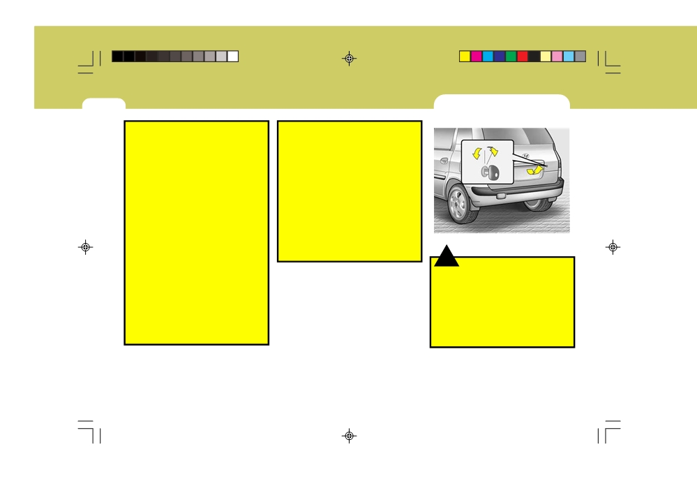
OUTSIDE REARVIEW MIRROR
FOLDING THE OUTSIDE REAR
HEATER (Not all models)
VIEW MIRRORS
B510D01E
!
HFC2080-D
B510C01FC-D
CAUTION:
o Do not leave the switch on for an
The outside rearview mirror heater is
To fold the outside rear view mirrors,
unnecessary length of time.
actuated in connection with the rear
push them towards the rear.
o Scraping ice from the mirror face
window defroster. To heat the outside
The outside rear view mirrors can be
could cause permanent damage.
rearview mirror glass, push in the switch
folded rearward for parking in restricted
To remove any ice, use a sponge,
for the rear window defroster. The rear-
areas.
soft cloth or approved deicer.
view mirror glass will be heated for
defrosting or defogging and will give
you improved rear vision in inclement
!
WARNING:
!
weather conditions. Push the switch
WARNING:
Do not adjust or fold the outside rear
again to turn the heater off. The outside
Be careful when judging the size or
view mirrors whilst the vehicle is
rearview mirror heater automatically
distance of any object seen in the
moving. This could result in loss of
turns itself off after 20 minutes.
passenger side rear view mirror. It is
control, and an accident causing
a convex mirror with a curved sur-
death, serious injury or property
face, any objects seen in this mirror
damage.
are closer than they appear.
fcuk-1.p65
68
12/27/2006, 10:12 AM

CONTROLS AND EQUIPMENT
1
SUN VISOR
69
SB370A1-E
B580A01E-EAT
NOTE:
INTERIOR REAR VIEW MIRROR
The Supplemental Restraint System
(SRS) label containing useful infor-
mation can be found on the back of
each sun visor.
!
WARNING:
Do not place the sun visor in such a
Vanity mirror
manner that it obscures visibility of
the roadway, traffic or other objects.
HFC2094-D
HXDFL2112
Sun visors are fitted to both the driver
The interior mirror is of the day/night
and passenger side of the vehicle. Cer-
type to enable the glare of headlights
tain derivatives are equipped with a
from following vehicles to be eliminated
vanity mirror which is located on the
during night time driving.
back of the driver and passenger visor.
The tab located at the bottom of the
The visor may be lowered to reduce the
mirror should be set to the position
amount of glare from directly ahead, or
nearest the windscreen for normal day
may be moved towards the side window
time driving, and flipped towards the
to reduce glare from the side of the
rear of the vehicle to eliminate glare
vehicle, once the inner pivot has been
during night time driving. To adjust the
unclipped from the bracket.
field of vision, the mirror may be moved
by hand upon the mounting.
NOTE:
The mirror should always be ad-
justed prior to setting the vehicle in
motion.
fcuk-1.p65
69
12/27/2006, 10:12 AM

1 CONTROLS AND EQUIPMENT
FOLD-UP TRAY
HIGH-MOUNTED REAR STOP
BONNET RELEASE
70
LIGHT
B810A01FC-GAT
B550A01S-EAT
B570A01FC-EAT
HFC2070
B550A02FC
HFC2018-D
For your convenience, it may be used
In addition to the lower-mounted rear
Pull the release lever inside the vehicle
as a table holding a book, cup or can.
stoplights on either side of the car, the
to unlatch the bonnet. At the front of the
high mounted rear stoplight in the cen-
vehicle, push the safety catch lever
tre of the rear window or inserted in the
sidewards as shown and raise the bon-
rear spoiler also lights when the brakes
net by hand. Support the bonnet by
!
WARNING:
are applied.
means of the bonnet prop.
To avoid the possibility of injury in
Before closing the bonnet, ensure that
case of an accident or a sudden stop,
the prop is correctly stowed. Lower the
the fold-up tray should be place its
bonnet by hand to a position of approxi-
original position whilst the vehicle
mately 30cm from the closed position
is moving.
and allow the bonnet to drop. Do not
attempt to close the bonnet by lowering
the panel to the closed position and
pressing upon the panel work since this
may result in damage to the panel.
fcuk-1.p65
70
12/27/2006, 10:12 AM

CONTROLS AND EQUIPMENT
1
REMOTE FUEL FILLER FLAP
71
RELEASE
SB440A2-E
(Not all models)
HFC203
HFC2016
HFC2015-D
The fuel filler flap may be opened from
!
!
CAUTION:
inside the vehicle by pulling up on the
WARNING:
Ensure that the bonnet prop has
fuel filler flap release.
o Petrol vapors are dangerous. Be-
been removed prior to closing the
fore refueling, always stop the en-
bonnet. Always check to ensure that
NOTE:
gine and never allow sparks or
the bonnet has latched prior to set-
If the fuel filler flap will not open
open flames near the filler area. If
ting the vehicle in motion.
because ice has formed around it,
you need to replace the filler cap,
tap lightly or push on it to break the
use a genuine Hyundai replace-
ice and release it. Do not lever the
ment part.
flap. If necessary, spray around the
If you open the fuel filler cap dur-
!
flap with an approved deicer fluid
ing high ambient temperatures, a
WARNING:
(do not use radiator anti-freeze) or
slight "pressure sound" may be
The bonnet prop must be correctly
move the vehicle to a warm place
heard. This is normal and not a
inserted into the panel to prevent the
and allow the ice to melt.
cause for concern.
possibility of injury arising from the
Whenever you open the fuel filler
bonnet falling.
cap, turn it slowly.
fcuk-1.p65
71
12/27/2006, 10:12 AM
1 CONTROLS AND EQUIPMENT
HATCHBACK DOOR
72
B540A01FC-EAT
o Automotive fuels are flammable/
o Do not use cellular phones around
explosive materials. When refuel-
a gas station. The electric current
ing, please note the following
or electronic interference from
UNLOCK
guidelines carefully.
cellular phones can ignite fuel
o Before touching the fuel nozzle or
vapors causing a fire.
LOCK
fuel filler cap, have one's hands in
o When refueling always shut the
contact with metal parts away from
engine off. Sparks by electrical
the filler neck to discharge static
equipment of the engine can ig-
electricity.
nite fuel vapors causing a fire.
o Do not get back in the vehicle
After refueling, check to make sure
whilst refueling. Do not operate
the fuel filler cap is securely closed,
anything that can produce static
and then start the engine.
B540A02FC
electricity. Static electricity dis-
o Do not smoke or try to light ciga-
charge can ignite fuel vapors re-
rettes around a gas station. Auto-
sulting in explosion.
motive fuels are flammable.
!
o When using a portable fuel con-
WARNING:
tainer be sure to place the con-
The hatchback door should always
tainer on the ground whilst refuel-
be kept completely closed whilst the
ing. Static electricity discharge
vehicle is in motion. If it is left open
from the container can ignite fuel
or ajar, poisonous exhaust gases
vapors causing a fire. Whilst start-
may enter the car resulting in seri-
ing refueling contact should be
ous illness or death to the occu-
maintained until the filling is com-
pants. See additional warnings con-
plete.
cerning exhaust gases on page 2-2.
fcuk-1.p65
72
12/27/2006, 10:12 AM

CONTROLS AND EQUIPMENT
1
LUGGAGE NET
73
o
The hatchback door can be locked or
B540D03FC-DAT
unlocked with a key.
!
o
The hatchback door is opened by
WARNING:
pulling the outside handle up, raising
Avoid eye injury. DO NOT over-
the hatchback door manually.
stretch. ALWAYS keep face and body
o
To close, lower the hatchback door,
out of recoil path. DO NOT use when
then press down on it until it is
strap has visible signs of wear or
closed. To be sure the hatchback
damage.
door is fully closed, always try to pull
it up again without using the outside
handle.
B540D01HP
Some objects can be kept in the net in
the luggage compartment.
Use the luggage net on the floor or at the
back of the luggage compartment to
prevent the objects from sliding.
!
CAUTION:
To prevent damage to the goods or
the vehicle, care should be taken
when carrying fragile or bulky ob-
jects in the trunk.
fcuk-1.p65
73
12/27/2006, 10:12 AM

1 CONTROLS AND EQUIPMENT
CARGO AREA COVER
ROOF RACK
74
B650A01FC-EAT
B630A03FC-EAT
(Not all models)
34 kg (75 lb)
ROOF RACK
EVENLY DISTRBUTED
o Loading cargo or luggage above
34 kg (75 lb) on the roof rack may
damage your vehicle.
When you carry large objects,
never let them hang over the rear
or the sides of your vehicle.
o To prevent damage or loss of cargo
as you are driving, check fre-
B640A02FC
quently to make sure the luggage
HFC2106
Nothing should be carried on top of the
carrier and cargo are still securely
luggage cover. Loose materials could
If your Hyundai has a roof rack, you can
fastened.
result in injury to vehicle occupants
load things on top of your vehicle.
o Always drive your vehicle at a
during sudden braking.
Crossrails and fixing components to
moderate speed.
adapt the roof rack on your vehicle may
o To use the roof rails as a roof rack,
be obtained from an Hyundai authorised
you must fit the roof rails with two
repairer.
or more crossrails or equivalent
before carrying cargo or lugguage
on the roof.
o When crossrail is adapted, you
!
CAUTION:
can load items on the roof rack.
o The following specifications are
o Loading cargo or luggage over
recommended when loading cargo
specification on the roof rack may
or luggage.
damage stability of your vehicle.
o In case the sunroof is equipped,
do not position roof rack loads
that could interfere with opening
of the sunroof.
fcuk-1.p65
74
12/27/2006, 10:12 AM

CONTROLS AND EQUIPMENT
1
AUTO FUEL CUT SWITCH
STEERING WHEEL TILT LEVER
HORN
75
B560B01O-GAT
SB520A1-F
B610A01S-EAT
(Petrol Engine)
With Airbag
HFC2041
HFC2099
HFC4001
Press the pad of the steering wheel to
To adjust the steering wheel:
The auto fuel cut switch is located on the
sound the horn.
driver's side of the engine compartment.
1. Push the lever downward to unlock.
In the event of a collision or sudden
2. Raise or lower the steering wheel to
impact, the auto fuel cut device cuts off
the desired position.
the fuel supply. If this device is acti-
3. After adjustment, securely tighten
vated, it must be reset by pressing in on
the lever by pulling it upward
the top of the switch before the engine
can be restarted.
!
WARNING:
!
Do not attempt to adjust the steering
WARNING:
wheel whilst driving as this may
Before resetting the auto fuel cut
result in loss of control of the vehicle
switch, the fuel line should be
and result in death or serious injury.
checked for fuel leaks.
fcuk-1.p65
75
12/27/2006, 10:12 AM

1 CONTROLS AND EQUIPMENT
HEATING AND COOLING CONTROL
76
B710A01Y-EAT
B710B01A-DAT
(Not all models)
CENTRE VENTILATOR
The centre ventilators are located in the
middle of the dashboard.
To change the direction of the air flow,
turn the control knob on the middle of
the ventilator as desired.
B710C01FC-EAT
SIDE VENTILATOR
The side ventilators are located on
each side of the dashboard. To change
the direction of the air flow, move the
knob in the centre of the vent. The
vents are opened when the vent knob is
moved to " " position. The vents are
closed when the vent knob is moved to
"
". Keep these vents clear of any
obstructions.
HFC002-D
1. Side Ventilator
2. Side Defrost Nozzle
3. Centre Ventilator
4. Windscreen Defrost Nozzle
fcuk-1.p65
76
12/27/2006, 10:12 AM

CONTROLS AND EQUIPMENT
1
HEATING AND VENTILATION
77
B670A01FC-EAT
B670E01A-AAT
B670B01FC-AAT
Rotary Type (Not all models)
Temperature Control
Fan Speed Control
(Blower Control)
1
2
3
4
B670A01FC
HFC2066
This model has four controls for the
This is used to turn the heating system
HFC2065
heating and cooling system. They are:
on and off and to select the degree of
This is used to turn the blower fan on or
heating desired.
off and to select the fan speed.
1. Temperature control
This blower fan speed, and therefore
2. Fan speed control
the volume of air delivered from the
3. Air flow control
system, may be controlled manually by
4. Air intake control
setting the blower control between the
"1" and "4" positions.
"1" is lowest and "4" is the highest fan
speed.
fcuk-1.p65
77
12/27/2006, 10:12 AM