Honda Odyssey 2004. Manual - part 556
−
−
−
−
03
01
*01
02
YES
NO
YES
NO
23-166
SRS
DTC Troubleshooting (cont’d)
B
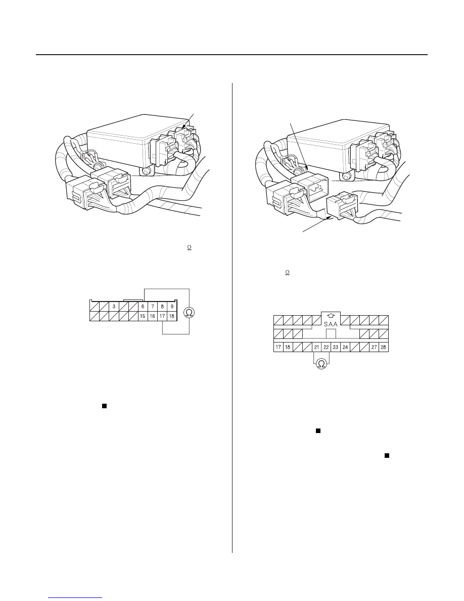
SRS UNIT CONNECTOR B (18P)
C852
A
SRS FLOOR SUBHARNESS 28P CONNECTOR
12. Disconnect SRS unit connector B (18P) from the
SRS unit.
13. Check resistance between the No. 6 and No. 17
terminals of SRS unit connector B (18P). There
should be an open circuit, or at least 1 M
.
Faulty SRS unit; replace the SRS unit (see
page 23-382).
Go to step 14.
14. Disconnect the SRS floor subharness 28P
connector (A) from the SRS floor harness 28P
connector C852.
15. Check resistance between the No. 21 and No. 22
terminals of the SRS floor subharness 28P
connector. There should be an open circuit, or at
least 1 M
.
Short in the SRS floor harness; replace the
SRS floor harness.
Short in the SRS floor subharness or left side
wire harness; replace the faulty harness.
Wire side of female terminals
Wire side of female terminals
Is the r esistance as specif ied?
Is the r esistance as specif ied?
03/07/29 10:36:13 61S0X050_230_0166