Honda Odyssey 2004. Manual - part 555
−
−
−
−
*02
13
*03
15
YES
NO
YES
NO
23-162
SRS
DTC Troubleshooting (cont’d)
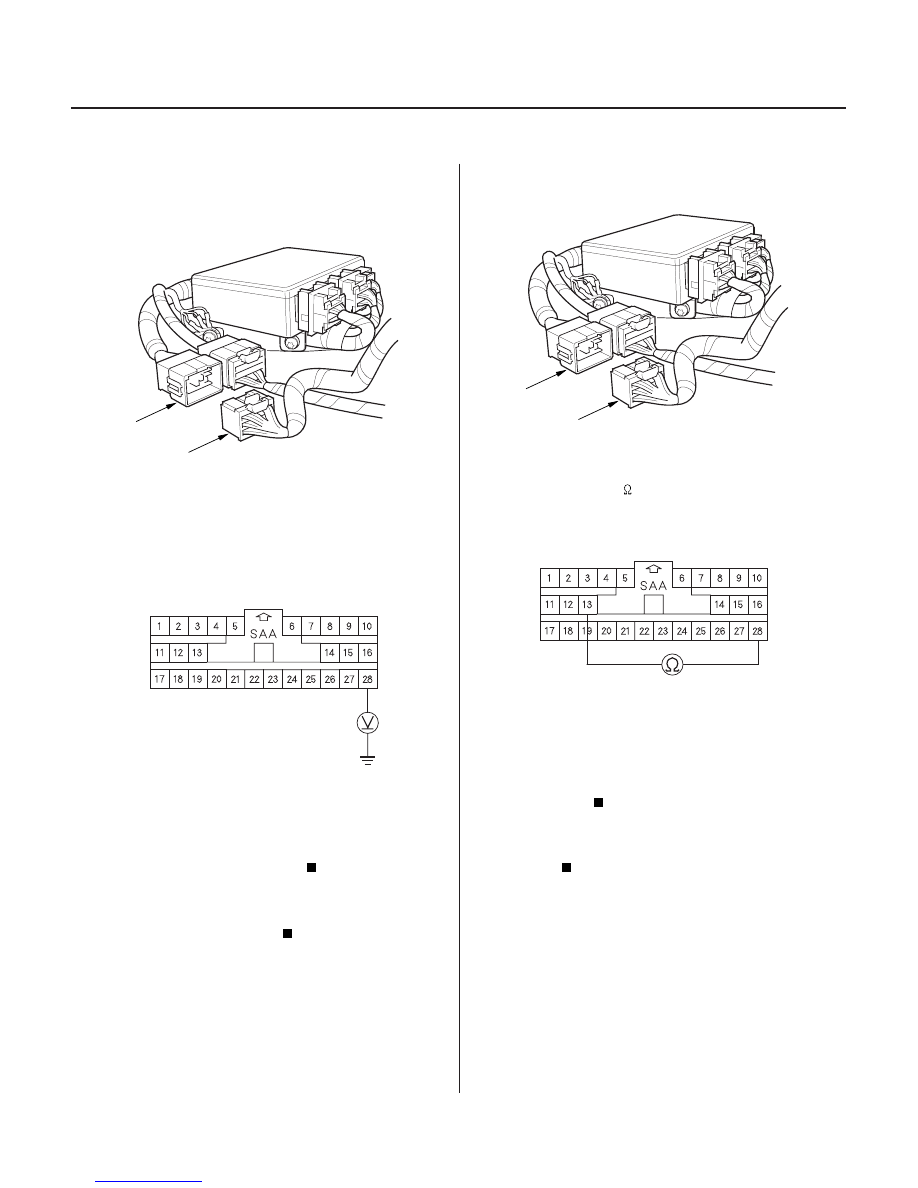
C851
A
SRS MAIN HARNESS 28P CONNECTOR
C851
A
SRS MAIN HARNESS 28P CONNECTOR
19. Turn the ignition switch OFF.
20. Disconnect the SRS main harness 28P connector
(A) from the SRS floor harness 28P connector C851.
21. Turn the ignition switch ON (II).
22. Check for voltage between the No. 28 terminal of
the SRS main harness 28P connector and body
ground. There should be 1 V or less.
Short to power in the SRS floor harness;
replace the SRS floor harness.
Short to power in the right engine
compartment wire harness or SRS main harness;
replace the faulty harness.
23. Disconnect the SRS main harness 28P connector
(A) from the SRS floor harness 28P connector C851.
24. Check resistance between the No. 13 and No. 28
terminals of the SRS main harness 28P connector.
There should be 1
or less.
Faulty SRS floor harness; replace the SRS
floor harness.
Faulty right engine compartment wire
harness or SRS main harness; replace the faulty
harness.
Wire side of female terminals
Wire side of female terminals
Is the voltage as specif ied?
Is the r esistance as specif ied?
03/07/29 10:36:11 61S0X050_230_0162