Honda Odyssey 2004. Manual - part 478


  Index      Honda     Honda Odyssey 2004 - service repair manual 2004 year


Search            


Content   ..  476  477  478  479   ..


Honda Odyssey 2004. Manual - part 478


01

S0X4A00J46636234501KBAT00

YES

NO

YES

NO

YES

NO

22-240

22-240

Immobilizer System

Troubleshooting (cont’d)

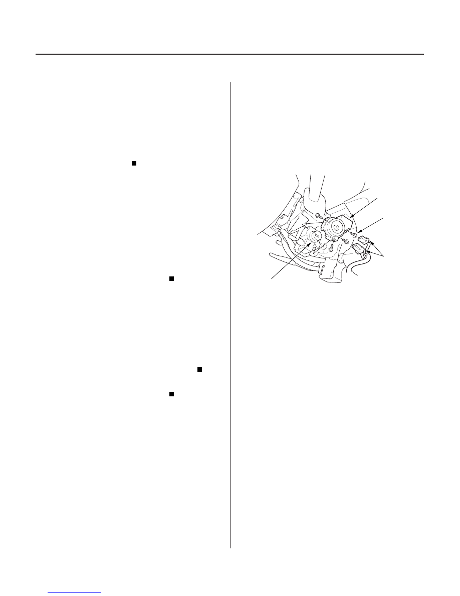
Immobilizer Receiver Unit
Replacement

B

A

C

D

6. Check for continuity between the No. 4 terminal

and body ground.

Go to step 7.

Repair open in the BRN/BLK or BRN/YEL

(’02-03 models) wire between the immobilizer
receiver unit and G101.

7. Check for continuity between the No. 2 terminal

and the PCM.

• (’99-00 models) connector A No. 25 terminal
• (’01 model) connector E No. 31 terminal
• (’02-04 models) connector E No. 2 terminal

Go to step 8.

Repair open in the RED wire between the

immobilizer receiver unit and PCM.

8. Check for continuity between the No. 3 terminal

and PCM.

• (’99-00 models) connector A No. 13 terminal
• (’01 model) connector E No. 30 terminal
• (’02-04 models) connector E No. 12 terminal

Replace the immobilizer receiver unit.

Repair open in the BLU wire between the

immobilizer receiver unit and PCM.

1. Remove the driver’s dashboard lower cover (see

page 20-69).

2. Remove the steering column covers (see page 17-

25).

3. Disconnect the 5P and 7P connectors (A) from the

immobilizer receiver unit (B).

4. Remove the screws (C) and the immobilizer

receiver unit from the ignition key cylinder (D).

5. Install in the reverse order of removal.

6. After replacement, check the immobilizer system.

NOTE: The PCM does not need to be
reprogrammed if only the receiver has been
replaced.

Is ther e continuity?

Is ther e continuity?

Is ther e continuity?

03/07/29 10:24:29 61S0X050_220_0242

*01

S0X4A00J00050600000DAAT00

22-241

Multiplex Control System

Component Location Index

PASSENGER’S MULTIPLEX CONTROL UNIT

IGNITION KEY LIGHT

DOOR MULTIPLEX CONTROL UNIT

DRIVER’S MULTIPLEX CONTROL UNIT

MULTIPLEX CONTROL INSPECTION CONNECTOR

(Has built-in beeper)

Test, page 22-145

(Built into the power window master
switch)

(Near the brake pedal)

03/07/29 10:24:30 61S0X050_220_0243

*01

S0X4A00J00050600000EAAT00

22-242

Multiplex Control System

Circuit Diagram (Power, Ground, Communication Lines)

(Fuse/relay box socket)

(Fuse/relay box socket)

* A19 : ’99 02 and ’03 04 (EX, EXL) models

: ’03 04 (LX) models

A13

IGNITION SWITCH

B1

B9

A2

A15

WHT/BLU

WHT/BLU

No.51 (40A)

BLK

No.15 (20A)

BLK

A12

G503

BLK

B22

B11

G501

BLK

A2

GRN/WHT

A12

BLK

G401

BEEPER

A22

YEL

6

7

No.13
(7.5A)

No.47 (20A)

No.54 (40A)

YEL

A1

WHT/YEL

G551

BLK

*

BRN

A12

WHT/YEL

(10A)

A8

BLK

G581

3

1

A15

BLU/WHT

PNK

A24

WHT/YEL

BLK

A24

G401

WHT/YEL

BLK

BLK

BLK

3

1

A13

A14

A1

WHT/BLK

No.9

BATTERY

No.42 (50A)

UNDER HOOD FUSE/RELAY BOX

IG1

BAT

No.41 (120A)

WHT

BLK/YEL

DRIVER’S
UNDER DASH
FUSE/RELAY BOX

PASSENGER’S
UNDER DASH
FUSE/RELAY
BOX

IGNITION
KEY LIGHT
(LED)

DOOR
MULTIPLEX
CONTROL UNIT

DRIVER’S
MULTIPLEX
CONTROL UNIT

PASSENGER’S
MULTIPLEX
CONTROL UNIT

POWER
WINDOW
RELAY

PASSENGER’S
UNDER DASH
FUSE/RELAY BOX

MULTIPLEX
CONTROL
INSPECTION
CONNECTOR

IGNITION
KEY
SWITCH

03/07/29 10:24:30 61S0X050_220_0244

S0X4A00J00050600000CAAT00

Multiplex Communication

Wake-up and Sleep

Fail-safe

22-243

System Descriptions

The multiplex control system has four internal
functions:

• Multiplexing (send multiple signals over shared

wires)

• Wake up/sleep modes (runs at full power only on

demand to reduce battery draw)

• Fail-safe (fixes or ignores faulty signals)
• Self-diagnosis (Mode 1 for the system, Mode 2 for

input lines)

The system controls the function of the following
circuits

• Engine Oil Pressure Indicator
• Seat Belt Reminder
• Lights-on Reminder
• Key-in Reminder
• Key Light Timer
• Dash Lights Brightness Control
• Entry Light Control (EX and EXL models)
• Automatic Lights-off (EX and EXL models)
• Power Window (including key-off timer operation)
• Wiper/Washers (including speed sensitive

intermittent wiper)

• Keyless/Power Door Locks
• Interlock
• Factory Security Alarm System (’01-04 EX and ’02-04

EXL models)

To reduce the number of wire harnesses, digital signals
are sent via shared multiplex communication lines
rather than sending normal electrical signals through
individual wires.

• The input signals from each switch are converted to

digital signals at the central processing unit (CPU).
The digital signals are sent from the transmitter unit
to the receiver unit as serial signals.

• The transmitted signal is converted to a switch signal

at the receiver unit, and it operates the related
component.

• There are exclusive communication lines between

each of the multiplex control units:
– Door

Driver’s (between the door and the driver’s

multiplex control units) Wire color: BRN

– Driver’s

Passenger’s (between the driver’s and

the passenger’s multiplex control units) Wire color:
PNK

The control units always communicate via these lines
when the system is operating, and they stop
communicating when the system is OFF.

The multiplex control system has ‘‘wake-up’’ and
‘‘sleep’’ functions to decrease parasitic draw on the
battery when the ignition switch is OFF.

• In the sleep mode, the multiplex control unit stops the

functions (communication and CPU control) when it
is not necessary for the system to operate.

• As soon as any operation is requested (for example,

door is unlocked), the related control unit in the sleep
mode immediately wakes up and begins to function.
This control unit also sends a wake-up signal to the
other control units via the communication lines.

• When the ignition switch is turned OFF, and driver’s

or front passenger’s door is opened then closed,
there is about a 10 second delay before the control
units go from the wake-up mode to the sleep mode.

• If any door is open, the sleep mode will not function.
• If a key is in the ignition switch, the sleep mode will

not function.

• If one of the key cylinder switch inputs is shorted, the

sleep mode will not function.

To prevent improper operation, the multiplex control
system has a fail-safe function. In the fail-safe mode,
the output signal is stopped when any part of the
system malfunctions (for example, a faulty control unit
or communication line).
Each control unit has a hardware fail-safe function that
stops the output signal when there is any CPU
malfunction, and a software fail-safe function that
ignores the signal from the malfunctioning control unit
and allows part of the system with no defect to operate
normally.

03/07/29 10:24:31 61S0X050_220_0245


Content   ..  476  477  478  479   ..