Honda Odyssey 2004. Manual - part 326
*90
S0X4A96D10600000000EAAT00
+
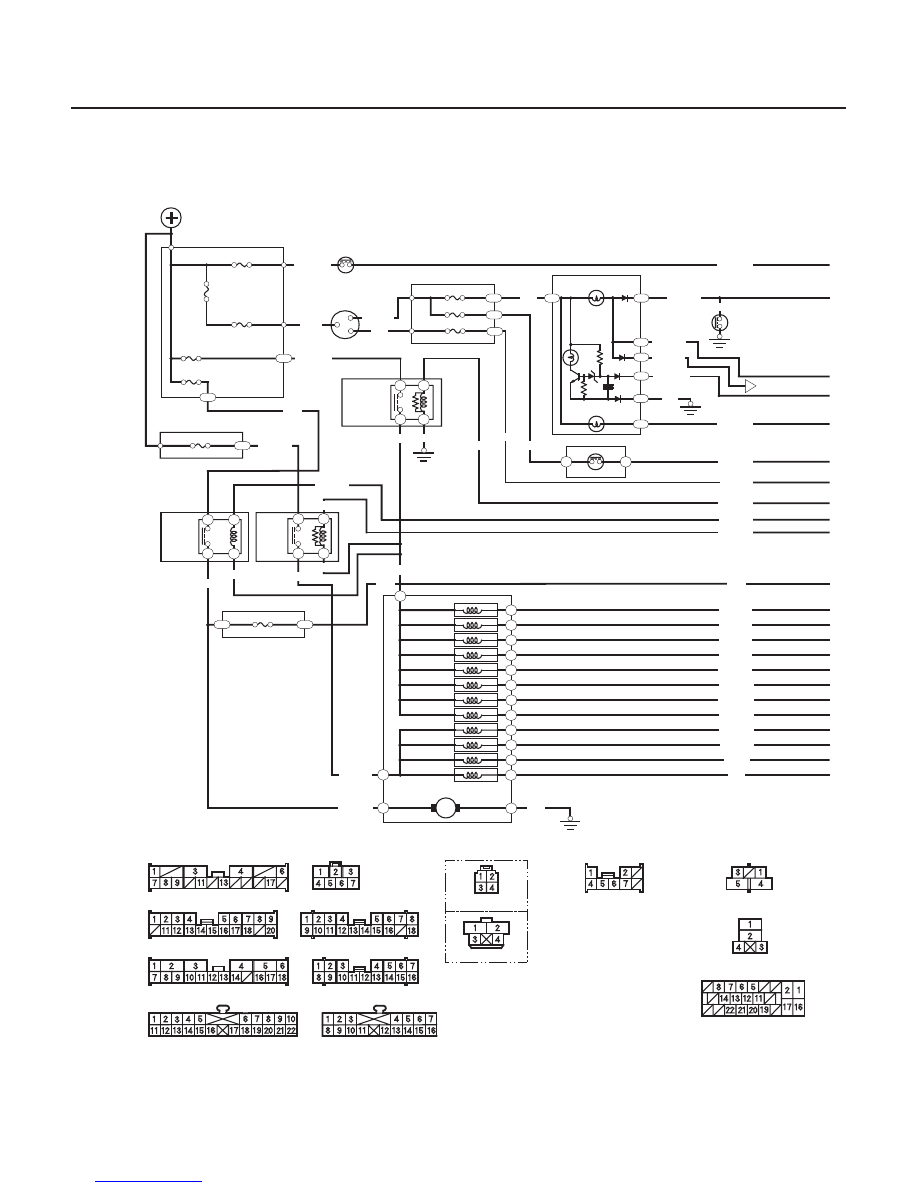
’02-04 models
19-110
ABS/TCS Components
Circuit Diagram (cont’d)
IG1
IG2
1
4
2
3
1
5
4
3
2
1
4
3
B1
A6
E16
H4
C4
J5
2
8
7
5
1
6
6
5
B11
C14
B8
C10
B16
B13
B14
I 4
I 12
2
3 (1 )
B
UNDER-HOOD FUSE/RELAY BOX
STOP (20A)
BATTERY (120A)
IG1 MAIN (50A)
ABS F/S (20A)
ABS MOTOR (30A)
BRAKE PEDAL POSITION SWITCH
Closed: Brake pedal pressed
IGNITION
SWITCH
DRIVER’S UNDER-DASH
FUSE/RELAY BOX
R/C MIRROR (7.5A)
UNDER-HOOD
ABS RELAY BOX
FAIL-SAFE
RELAY
BRN/BLK BLK
BACKUP LIGHT (10A)
PASSENGER’S UNDER-DASH
FUSE/RELAY BOX
BSC (10A)
WHT/GRN
WHT
YEL
YEL
WHT
WHT/YEL
TCS
RELAY
ABS
PUMP
MOTOR
RELAY
UNDER-HOOD
ABS RELAY BOX
PASSENGER’S UNDER-DASH
FUSE/RELAY BOX
G201
MULTI-FUSE/
RELAY BOX
BLU/BLK
YEL/RED
GRN/YEL
RED/BLU
BRN/BLK
GRN
BRN/BLK
WHT/BLU
BLK/YEL
MODULATOR UNIT
PUMP MOTOR
G302
FL-IN
FL-OUT
FR-IN
RL-IN
FR-OUT
RL-OUT
RR-IN
RR-OUT
NOL
NCL
NCR
NOR
BRN/BLK
RED/BLU
WHT/BLU
BLK
GRN
RED/BLU
YEL/BLU
RED/BLK
YEL/BLK
RED/GRN
YEL/GRN
RED/WHT
YEL/WHT
RED/GRN
YEL/GRN
LT BLU
GRY
TCS SWITCH
TCS INDICATOR
BRAKE SYSTEM
INDICATOR
GAUGE ASSEMBLY
BRAKE FLUID
LEVEL SWITCH
Closed: Low fluid
ALTERNATOR
GRN/RED
GRN/RED
YEL/WHT
BLU/WHT
BLK
RED/WHT
BLU/ORN
YEL/BLK
YEL/GRN
YEL/RED
GRN/YEL
WHT/BLK
*: ’04 model
’04 model
’02-03 models
YEL/BLK
YEL/GRN
BLK/YEL
*
ABS MOTOR CHECK (7.5A)
ABS
INDICATOR
G301
G503
WHT/BLU
RIGHT-REAR
SOLENOID
RIGHT TCS
SOLENOID
LEFT-FRONT
SOLENOID
RIGHT-FRONT
SOLENOID
LEFT TCS
SOLENOID
LEFT-REAR
SOLENOID
14
22
11
19
12
20
13
21
16
17
OUT
IN
OUT
IN
OUT
IN
OUT
IN
M
UNDER-HOOD FUSE/RELAY BOX CONNECTORS
CONNECTOR A (18P)
CONNECTOR B (7P)
BRAKE PEDAL POSITION
SWITCH CONNECTOR
DRIVER’S UNDER-DASH FUSE/RELAY BOX CONNECTORS
CONNECTOR I (18P)
CONNECTOR C (18P)
CONNECTOR B (22P)
PASSENGER’S UNDER-DASH FUSE/RELAY BOX CONNECTORS
CONNECTOR J (16P)
GAUGE ASSEMBLY CONNECTORS
CONNECTOR C (16P)
CRUISE CONTROL/
TCS SWITCH CONNECTOR
ABS PUMP MOTOR
RELAY CONNECTOR
ABS FAIL-SAFE RELAY/
TCS RELAY CONNECTOR
MODULATOR UNIT
CONNECTOR
CONNECTOR E (20P)
Wire side of female terminals
Terminal side of female terminals
03/07/29 09:57:31 61S0X050_190_0110