Honda Odyssey 2004. Manual - part 315


  Index      Honda     Honda Odyssey 2004 - service repair manual 2004 year


Search            


Content   ..  313  314  315  316   ..


Honda Odyssey 2004. Manual - part 315


02

*01

*02

03

YES

NO

YES

NO

YES

NO

YES
NO

YES
NO

19-66

ABS Components

DTC Troubleshooting (cont’d)

PUMP MOTOR RELAY CONNECTOR

B

(WHT)

MOTOR
(WHT/BLU)

JUMPER WIRE

MOTOR (WHT/BLU)

PUMP MOTOR CONNECTOR

MOTOR (WHT/BLU)

PUMP MOTOR CONNECTOR

MOTOR GND (BLK)

PUMP MOTOR RELAY CONNECTOR

JUMPER
WIRE

B (WHT)

PMR (YEL/RED)

6. Connect the pump motor relay connector terminal

No. 4 to No. 5 with a jumper wire for a moment,
and check the fuse.

Check for a short to body ground in the MCK

circuit.

Go to step 7.

7. Check the pump motor relay in the under-hood

ABS relay box (see page 22-88).

Go to step 8.

Replace the pump motor relay.

8. Connect the pump motor relay connector terminal

No. 4 to No. 5 with a jumper wire for a moment.

Go to step 13.

Go to step 9.

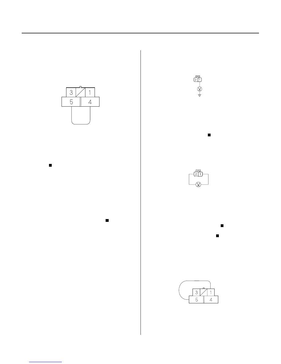
9. Disconnect the pump motor connector.

10. Connect the pump motor relay connector terminal

No. 4 to No. 5 with a jumper wire.

11. Measure the voltage between the pump motor

connector terminal No. 1 and body ground.

Go to step 12.

Repair open in the wire between the ABS

relay box and pump motor.

12. Measure the voltage between the pump motor

connector terminal No. 1 and No. 2.

Replace the modulator unit.

Repair open in the wire between the pump

motor and body ground (G302).

13. Disconnect the pump motor connector.

14. Connect the pump motor relay connector terminal

No. 1 to No. 5 with a jumper wire.

Terminal side of female terminals

Terminal side of female terminals

Terminal side of female terminals

Terminal side of female terminals

Is the f use blown?

Is the r elay OK ?

Does the pump motor oper ate?

Is ther e batter y voltage?

Is ther e batter y voltage?

03/07/29 09:55:51 61S0X050_190_0066

04

05

01

S0X4A07K70100081530FAAT00

YES

NO

YES

NO

YES

NO

YES

NO

YES

NO

DTC 53:

19-67

19-67

PMR (YEL/RED)

ABS CONTROL UNIT CONNECTOR B (12P)

PMR (YEL/RED)

ABS CONTROL UNIT CONNECTOR B (12P)

PASSENGER’S UNDER-DASH
FUSE/RELAY BOX CONNECTOR J (16P)

MCK (GRN)

15. Measure the voltage between the ABS control unit

connector B (12P) terminal No. 12 and body ground.

Go to step 16.

Repair open in the wire between the under-

hood ABS relay box and the ABS control unit.

16. Remove the jumper wire from the pump motor

relay connector.

17. Start the engine.

18. Measure the voltage between the ABS control unit

connector B (12P) terminal No. 12 and body ground.

Repair a short to power in the wire between

the under-hood ABS relay box and the ABS control
unit.

If the problem recurs, replace the ABS control

unit.

1. Check that the pump motor operates with the

ignition switch OFF.

Go to step 12.

Go to step 2.

2. Remove the ABS MOTOR CHECK (7.5A) fuse in the

passenger’s under-dash fuse/relay box.

Remove the fuse, and go to step 3.

Replace the fuse, and recheck.

3. Turn the ignition switch ON (II).

4. Measure the voltage between the passenger’s

under-dash fuse/relay box connector J (16P)
terminal No. 5 and body ground.

Go to step 5.

Repair open in the wire between the

passenger’s under-dash fuse/relay box and the
ABS control unit.

5. Reinstall the ABS MOTOR CHECK (7.5A) fuse in the

passenger’s under-dash fuse/relay box.

6. Disconnect the pump motor connector.

(cont’d)

Motor Stuck ON

Wire side of female terminals

Wire side of female terminals

Wire side of female terminals

Is ther e batter y voltage?

Is ther e batter y voltage?

Does the pump motor oper ate?

Is the f use OK ?

Is ther e about 10 V ?

03/07/29 09:55:51 61S0X050_190_0067

*01

*02

02

03

YES

NO

YES

NO

YES

NO

YES

NO

YES

NO

19-68

ABS Components

DTC Troubleshooting (cont’d)

PUMP MOTOR CONNECTOR

MOTOR (WHT/BLU)

MOTOR (WHT/BLU)

MOTOR GND (BLK)

PUMP MOTOR CONNECTOR

ABS CONTROL UNIT CONNECTOR B (12P)

PMR (YEL/RED)

ABS CONTROL UNIT CONNECTOR B (12P)

PMR (YEL/RED)

7. Measure the voltage between terminal No. 1 and

body ground.

Go to step 8.

Repair open in the wire between the under-

hood ABS relay box and the pump motor.

8. Measure the voltage between the pump motor

connector terminal No. 1 and No. 2.

Go to step 9.

Repair open in the wire between the pump

motor and body ground (G302).

9. Remove the pump motor relay, then connect relay

terminals No. 4 and No. 5 together with a jumper
wire.

Go to step 10.

Replace the pump motor.

10. Disconnect the ABS control unit connector B (12P).

11. Check for continuity between terminal No. 12 and

body ground.

Repair short to body ground in the wire

between the under-hood ABS relay box and the
ABS control unit.

If the problem recurs, replace the ABS control

unit.

12. Disconnect the ABS control unit connector B (12P).

13. Check for continuity between terminal No. 12 and

body ground.

Repair short to body ground in the wire

between the under-hood ABS relay box and the
ABS control unit.

Replace the pump motor relay (Pump motor

relay stuck ON).

Terminal side of female terminals

Terminal side of female terminals

Wire side of female terminals

Wire side of female terminals

Is ther e about 10 V ?

Is ther e about 10 V ?

Does the pump motor r un?

Is ther e continuity?

Is ther e continuity?

03/07/29 09:55:52 61S0X050_190_0068

01

02

*01

S0X4A07K70100081540FAAT00

DTC 54:

YES

NO

YES

NO

YES

NO

YES

NO

YES

NO

19-69

ABS FAIL-SAFE RELAY CONNECTOR

B (WHT/GRN)

ABS FAIL-SAFE RELAY CONNECTOR

B (WHT/GRN)

SOLENOID
(BRN/BLK)

JUMPER WIRE

MODULATOR UNIT CONNECTOR

SOLENOID
(BRN/BLK)

ABS Fail-safe Relay

1. Check the ABS F/S (20A) fuse in the under-hood

fuse/relay box, and reinstall the fuse if it is OK.

Go to step 2.

Replace the fuse, and recheck.

2. Reinstall the fuse, and turn the ignition switch ON

(II).

Repair short to body ground in the wire

between the ABS fail-safe relay, pump motor relay,
and modulator unit.

Go to step 3.

3. Check the ABS fail-safe relay in the multi-relay box

(see page 22-88). The wire colors of the ABS fail-
safe relay connector are WHT/GRN, BRN/BLK, BLK,
and YEL/GRN.

Leave the ABS fail-safe relay removed, and

go to step 4.

Replace the ABS fail-safe relay.

4. Measure the voltage between the ABS fail-safe

relay connector terminal No. 1 and body ground.

Go to step 5.

Repair open in the wire between the under-

hood fuse/relay box and the ABS fail-safe relay.

5. Connect the ABS fail-safe relay connector terminal

No. 1 to No. 2 with a jumper wire.

6. Disconnect the modulator unit connector.

7. Measure the voltage between terminal No. 10 and

body ground.

Go to step 8.

Repair open in the wire between the ABS fail-

safe relay and the modulator unit.

8. Remove the jumper wire from the ABS fail-safe

relay connector.

(cont’d)

Terminal side of female terminals

Terminal side of female terminals

Terminal side of female terminals

Is the f use OK ?

Does the f use blow?

Is the r elay OK ?

Is ther e batter y voltage?

Is ther e batter y voltage?

03/07/29 09:55:53 61S0X050_190_0069


Content   ..  313  314  315  316   ..