Honda Odyssey 2004. Manual - part 298
02
S0X4A00B44100056301KBAT00
Exploded View
18-32
Rear Suspension
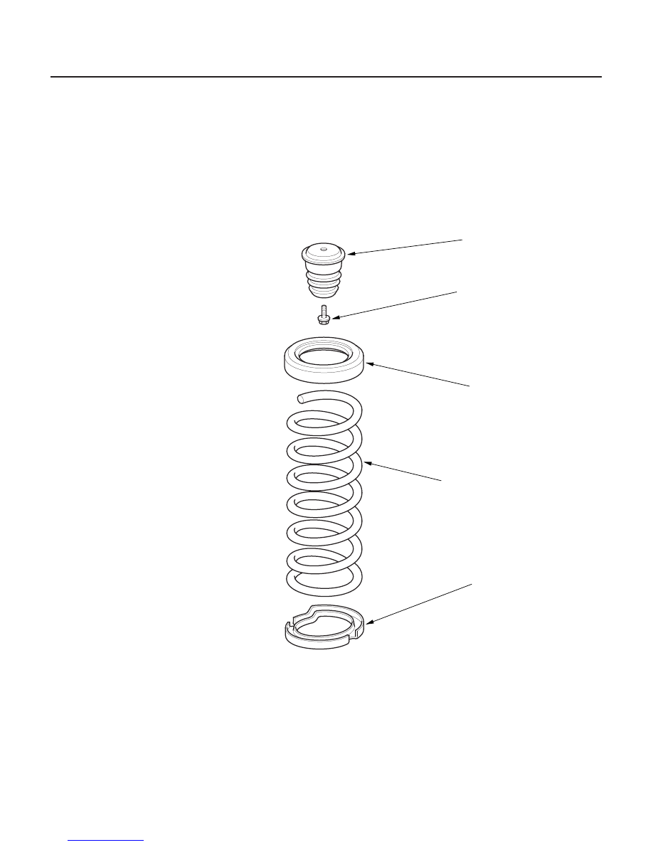
Spring/Bump Stop Replacement
SPRING
BUMP STOP
10 x 1.25 mm
39 N·m
(4.0 kgf·m, 29 lbf·ft)
SPRING UPPER SEAT
SPRING LOWER SEAT
Check for weakened compression
and damage.
Check for weakness
and damage.
Check for deterioration
and damage.
Check for deterioration
and damage.
03/07/29 09:51:23 61S0X050_180_0032