Honda Odyssey 2004. Manual - part 297


  Index      Honda     Honda Odyssey 2004 - service repair manual 2004 year


Search            


Content   ..  295  296  297  298   ..


Honda Odyssey 2004. Manual - part 297


*02

22

*04

*03

S0X4A00B44100037701KDAT25
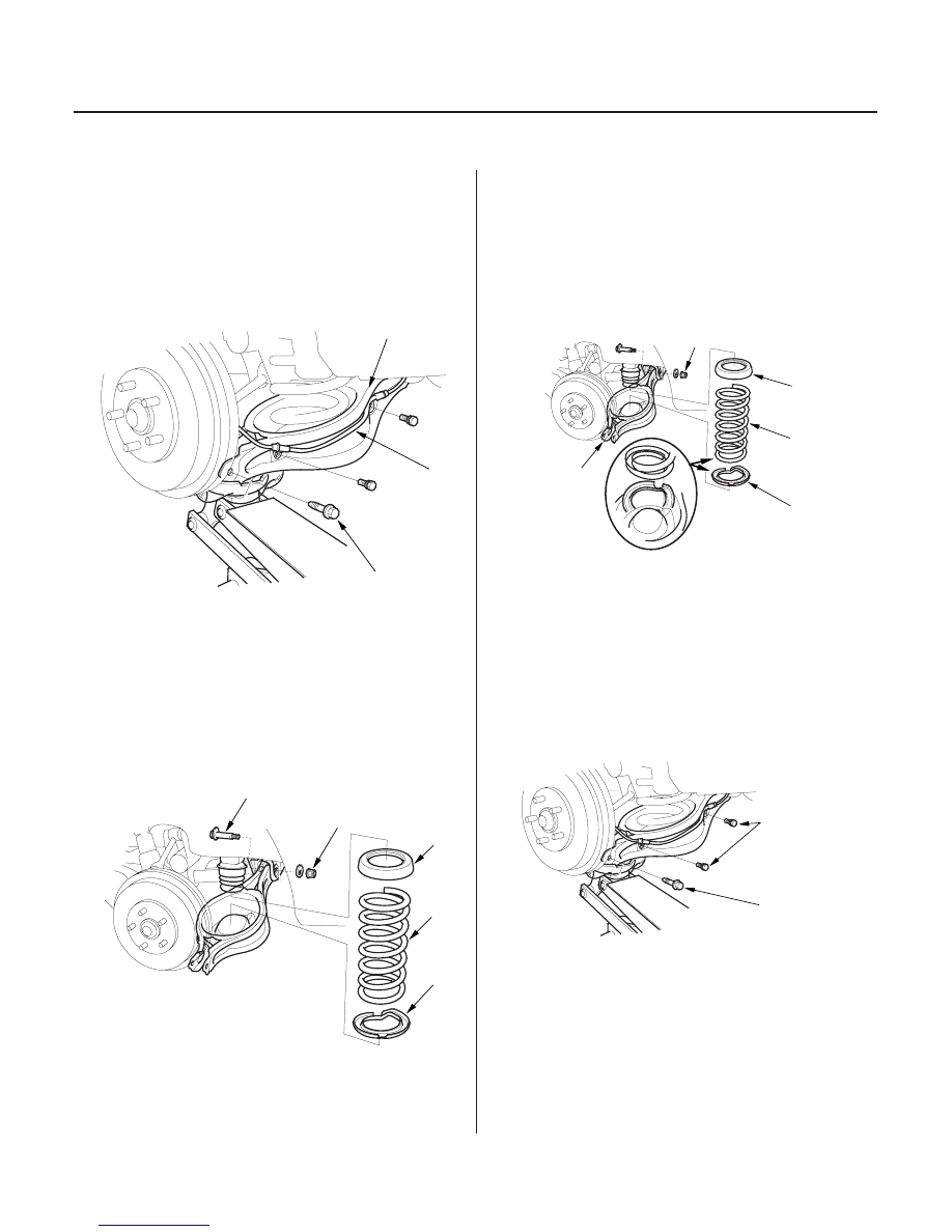
Removal

Installation

18-28

Rear Suspension

Lower Arm B Removal and Installation

B

A

C

C

A

B

D

E

12 x 1.25 mm
83 N·m (8.5 kgf·m, 61 lbf·ft)

C

B

D

A

6 x 1.0 mm
9.8 N·m
(1.0 kgf·m,
7.2 lbf·ft)

A
12 x 1.25 mm
74 N·m
(7.5 kgf·m,
54 lbf·ft)

1. Raise the rear of the vehicle, and support it with

safety stands in the proper locations
(see page 1-15). Remove the rear wheel.

2. Position a floor jack at the connecting point of

lower arm B and the knuckle.

3. Remove the wheel sensor (A) from the lower arm B.

Do not disconnect the wheel sensor connector.

4. Remove the flange bolt (C) that connects the lower

arm B and the knuckle.

5. Lower the floor jack gradually.

6. Remove the spring (A), upper spring seat (B) and

lower spring seat (C).

7. Remove the self-locking nut (D) and flange bolt (E).

1. Lower the rear suspension, position the lower arm

B, and loosely install the self-locking nut.

2. Install the spring (A), and upper spring seat (C).

Align the bottom of the spring and the lower spring
seat (D) with the lower arm B as shown.

3. Position a floor jack at the connecting point of the

lower arm B and the knuckle.

4. Align the bolt hole with the holes in the lower arm

B and the knuckle by raising the flange bolt.

5. Raise the rear suspension with a floor jack until the

vehicle just lifts off the safety stands.

6. Tighten the flange bolt (A) and self-locking nut.

7. Install the wheel sensor.

8. Install the rear wheel.

9. Check the rear wheel alignment, and adjust it if

necessary (see page 18-5).

03/07/29 09:51:21 61S0X050_180_0028

*01

*02

S0X4A00B44100059701KDAT00

18-29

Trailing Arm Removal/Installation

C
9.8 N·m
(1.0 kgf·m, 7.2 lbf·ft)

A
9.8 N·m
(1.0 kgf·m, 7.2 lbf·ft)

B

A
12 x 1.25 mm
64 N·m
(6.5 kgf·m, 47 lbf·ft)

B
14 x 1.5 mm
103 N·m
(10.5 kgf·m, 75.9 lbf·ft)

1. Raise the rear of the vehicle, and support it with

safety stands in the proper locations
(see page 1-15).

2. Remove the brake drum or brake disc/drum.

Drum brake (see step 1 on page 18-23).
Disc brake (see step 1 on page 18-24).

3. Remove the parking brake cable (A) from the

trailing arm (B).

4. Remove the brake hose mounting bolts (C) from

the trailing arm.

5. Position a floor jack at the connecting point of the

lower arm and the knuckle.

6. Remove the flange bolts (A) and (B) from the

trailing arm.

7. Install the trailing arm in the reverse order of

removal, and note these items:

• Tighten all mounting hardware to the specified

torque values.

• Check the brake hose and line joint for leaks, and

tighten if necessary.

• Check the brake hose for interference and

twisting.

• Before installing the wheel, clean the mating

surfaces on the brake drum or the drum in brake
disc and the inside of the wheel.

• Fill up the brake reservoir, and bleed the brake

system.

• After installation, check for leaks at the line joint,

and retighten if necessary. Check the rear wheel
alignment, and adjust it if necessary (see page
18-5).

03/07/29 09:51:21 61S0X050_180_0029

*01

12

S0X4A00B44100019102KDAT10

Removal

Inspection

18-30

Rear Suspension

Damper Removal and Installation

A

B

C

D

1. Raise the rear of the vehicle, and support it with

safety stands in the proper locations
(see page 1-15). Remove the rear wheel.

2. Position a floor jack at the connecting point of the

lower control arm and knuckle (A). Raise the floor
jack until the suspension begins to compress.

3. Remove the flange bolt (B) from the body.

4. Remove the self-locking nut (C) from the knuckle.

5. Compress the damper (D) by hand, and remove it

from the vehicle.

1. Push on the damper as shown.

2. Compress the damper assembly by hand, and

check for smooth operation through a full stroke,
both compression and extension. The damper
should move smoothly, if it does not
(no compression or no extension), the gas is
leaking, and the damper should be replaced.

3. Check for oil leaks, abnormal noises, or binding

during these tests.

03/07/29 09:51:22 61S0X050_180_0030

*02

Installation

18-31

B
12 x 1.25 mm
64 N·m (6.5 kgf·m, 47 lbf·ft)

A

C
12 x 1.25 mm
64 N·m
(6.5 kgf·m,
47 lbf·ft)

1. Lower the rear suspension. Compress the damper

(A) by hand, and move it into position. Loosely
install the flange bolt (B) and self-locking nut (C).

2. Raise the rear suspension with a floor jack until the

vehicle just lifts off the safety stands.

3. Tighten the flange bolt and self-locking nut on the

bottom of the damper to the specified torque value.

4. Install the rear wheel.

5. Check the rear wheel alignment, and adjust it if

necessary (see page 18-5).

03/07/29 09:51:22 61S0X050_180_0031


Content   ..  295  296  297  298   ..