Honda Odyssey 2004. Manual - part 285
−
−
−
*01
01
*01
S0X4A00F00000057141KBAT00
Preload:
70
90 N (7
9 kgf, 15
20 lbf)
17-28
17-28
Power Steering
Steering Column/Tilt Lever
Inspection/Adjustment (cont’d)
Steering Lock Replacement
A
C
B
D
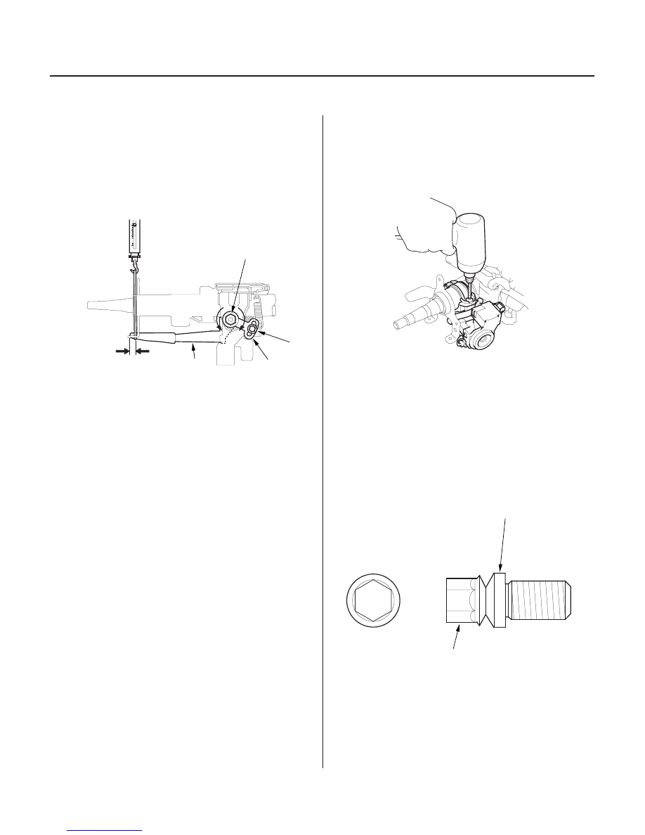
10 mm (0.4 in.)
A
B
1. Move the tilt lever (A) from the loose position to the
lock position 3 to 5 times; then measure the tilt
lever preload 10 mm (0.4 in.) from the end of the tilt
lever.
2. If the measurement is out of the specification,
adjust the preload using the following procedures.
• Loosen the tilt lever, and set the steering column
in the neutral position.
• Remove the 6 mm lock bolt (B), and remove the
stop (C). Be careful not to loosen the tilt lever
when installing the stop or tightening the 6 mm
lock bolt.
• Adjust the preload by turning the tilt lock bolt (D)
left or right.
• Pull up the tilt lever to the uppermost position,
and install the stop. Check the preload again. If
the measurement is still out of specification,
repeat the above procedures to adjust.
1. Remove the steering column (see page 17-25).
2. Center punch each of the two shear bolts, and drill
their heads off with a 5 mm (3/16 in.) drill bit. Be
careful not to damage the switch body when
removing the shear bolts.
3. Remove the shear bolts from the switch body.
4. Install the switch body without the key inserted.
5. Loosely tighten the new shear bolts.
6. Insert the ignition key, and check for proper
operation of the steering wheel lock and that the
ignition key turns freely.
7. Tighten the shear bolts (A) until the hex heads (B)
twist off.
03/07/29 09:49:07 61S0X050_170_0028