Honda Odyssey 2004. Manual - part 197
−
−
−
−
−
−
01
02
03
S0X4AA0E10436436021FAAT00
YES
NO
YES
NO
YES
NO
14-182
A/T Interlock System
Key Interlock System Circuit Troubleshooting
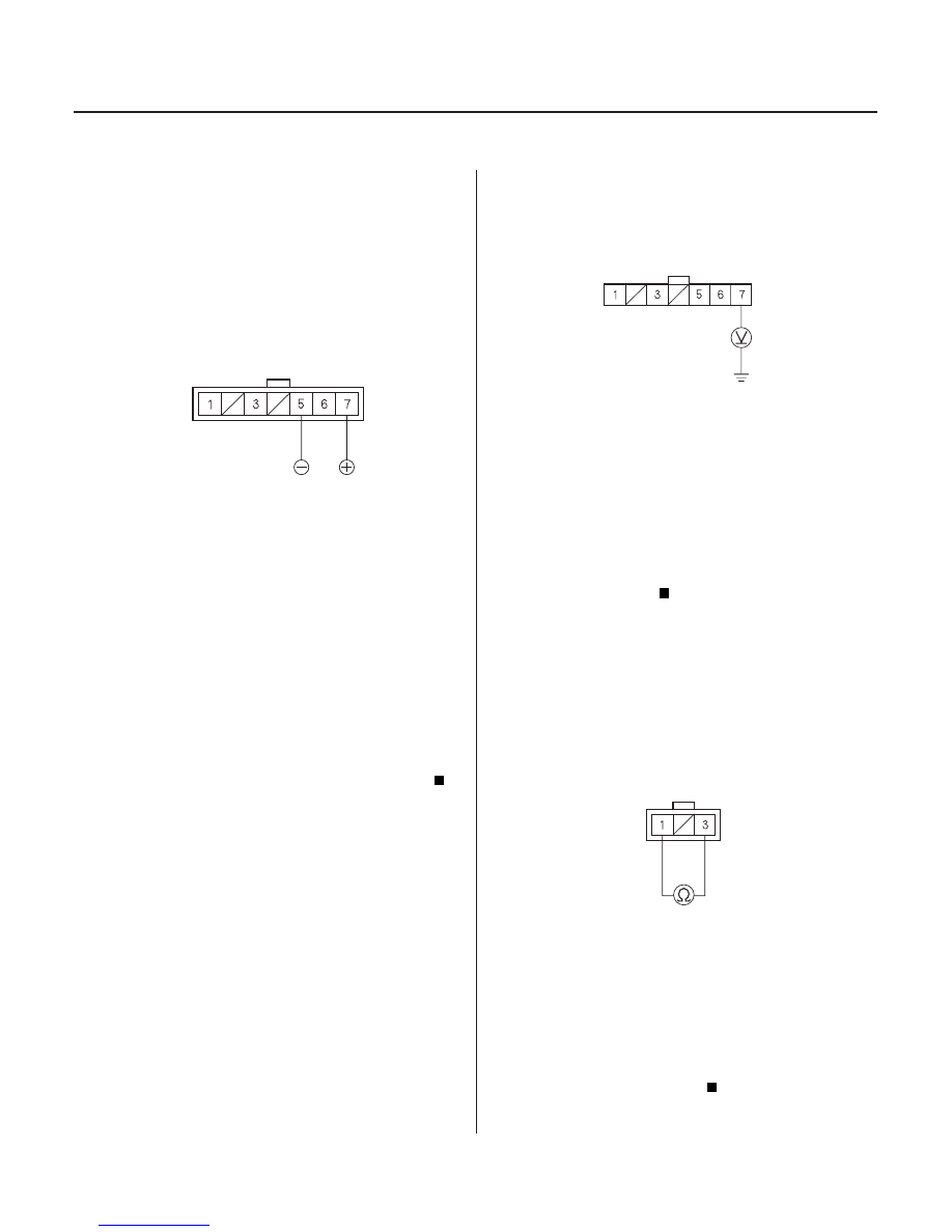
KEY SWITCH CONNECTOR (7P)
KEY SWITCH CONNECTOR (7P)
WHT/YEL
PARK PIN SWITCH CONNECTOR
1. Disconnect the key switch connector (7P) from the
steering lock assembly.
2. Connect the No. 7 terminal of the key switch
connector to the battery positive terminal, and
connect the No. 5 terminal to the battery negative
terminal.
3. Turn the ignition switch to ACC (I), then push the
ignition key.
4. Check the key interlock solenoid operation. A
clicking sound should be heard while pushing the
ignition key, and you should not be able to turn it to
the OFF position.
Go to step 5.
Faulty key interlock solenoid/switch. Replace
the ignition key cylinder/steering lock assembly.
5. Measure the voltage between the No. 7 terminal
and body ground.
Go to step 6.
Check for a blown No. 47 (20A) fuse in the
under-hood fuse/relay box. If the fuse is OK, repair
open or short in the wire between the No. 7
terminal of the key switch connector and under-
hood fuse/relay box.
6. Disconnect the park pin switch connector on the
shift lever.
7. With the shift lever in Park and pulled back toward
the driver, check for continuity between the No. 1
and No. 3 terminals of the park pin switch
connector.
Go to step 8.
Repair open in the wires between the park pin
switch and the connector. If the wires are OK,
replace the park pin switch .
Terminal side of male terminals
Wire side of female terminals
Terminal side of male terminals
Does the key inter lock solenoid oper ate pr oper ly?
Is ther e batter y voltage?
Is ther e continuity?
03/07/29 09:34:13 61S0X050_140_0185