Honda Odyssey 2004. Manual - part 195
01
*01
*02
*03
S0X4AA0E10410759811KBAT00
14-174
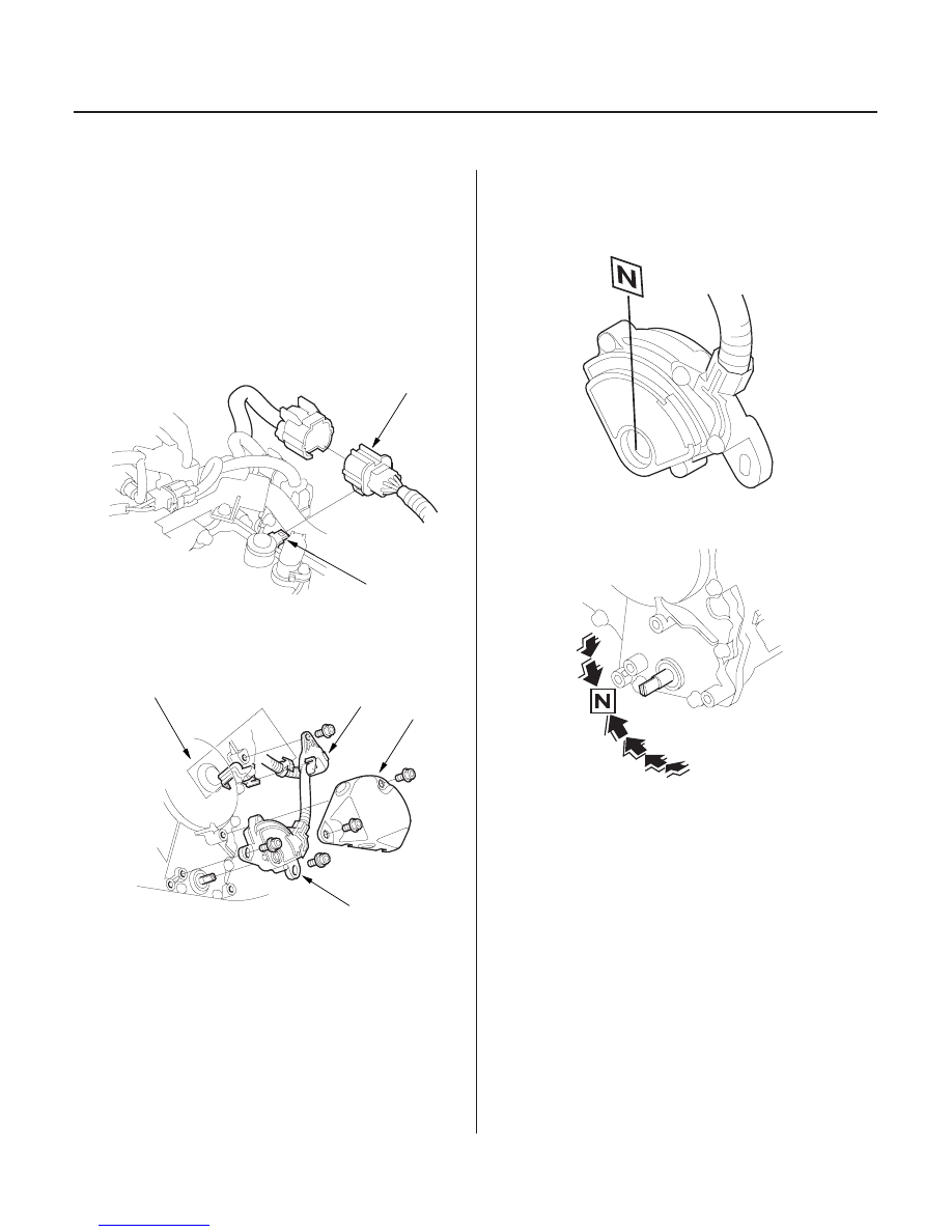
A/T Gear Position Indicator
Transmission Range Switch Replacement
B
A
B
A
C
D
1. Raise the front of the vehicle, and make sure it is
securely supported (see page 1-15).
2. Set the parking brake, and block both rear wheels
securely.
3. Shift to the N position.
4. Remove the transmission range switch connector
(A) from the connector bracket (B), then disconnect
the connector.
5. Remove the clamp from the harness clamp bracket
on the transmission housing, then remove the
harness clamp (A) from the end cover (B).
6. Remove the transmission range switch cover (C),
then remove the transmission range switch (D)
from the end cover.
7. Set the transmission range switch to the N position.
NOTE: The transmission range switch clicks in the
N position.
8. Set the control shaft to the N position.
03/07/29 09:34:06 61S0X050_140_0177