Honda Odyssey 2004. Manual - part 33
±
±
11
12
S0X4A08A14500017601KBAT01
01
04
S0X4A08A14500017602MBAT02
4-52
4-52
Cruise Control
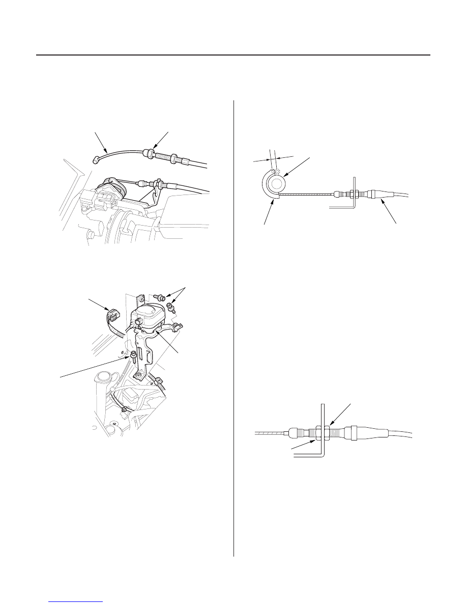
Cruise Control Actuator/Cable
Replacement
Cruise Control Actuator Cable
Adjustment
B
A
D
C
B
A
B
A
A
B
6 x 1.0 mm
12 N·m
(1.2 kgf·m,
8.7 lbf·ft)
B
6 x 1.0 mm
12 N·m
(1.2 kgf·m,
8.7 lbf·ft)
C
1. Loosen the locknut (A), then disconnect the
actuator cable (B) from the throttle linkage.
2. Disconnect the 4P connector (A) from the cruise
control actuator.
3. Remove the three mounting bolts (B), and remove
the cruise control actuator assembly (C).
4. Install actuator/cable in the reverse order of
removal, and adjust the free play at the throttle
linkage (see page 4-52) after connecting the
actuator cable.
1. Check that the actuator cable (A) moves smoothly
with no binding or sticking.
2. Start the engine, and turn the main switch ON. Hold
the engine at 3,000 rpm with no load in Park or
Neutral until the radiator fan comes on, then let it
idle.
3. Measure the amount of movement of the output
linkage (B) until the engine speed starts to increase.
At first, the output linkage should be located at the
fully closed position (C). The free play (D) should be
3.75
0.5 mm (0.15
0.02 in.).
4. If the free play is not within specification, move the
cable to the point where the engine speed starts to
increase, and tighten the locknut (A) and adjusting
nut (B).
03/07/29 09:08:26 61S0X050_040_0052