Content .. 1842 1843 1844 1845 ..
Ford F150 Pickup. Instruction - part 1844
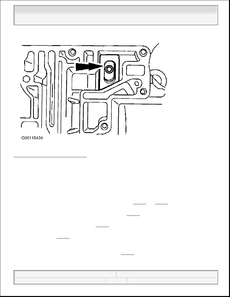
Fig. 51: Locating Pump Outlet Screen
Courtesy of FORD MOTOR CO.
Installation
1. Position the main control valve body gasket and main control valve body using the 2 alignment bolts as a
guide. Loosely install inner and outer valve body bolts. See Fig. 52 and Fig. 53 . The main control valve
body bolts will be tightened in later steps.
2. Install the instruction control valve detent lever spring. See Fig. 33 .
3. Position the instruction control valve detent lever spring and install the bolt. Tighten the main control valve
body bolts in the sequence shown. See Fig. 54 . Inspect the lead frame for damage.
4. Using the Transmission Solenoid Connector Gauge (307-426), check all the lead frame solenoid
connections. See Fig. 55 . The gauge should fit tightly and not fall out after being inserted. If the special
tool passes through any lead frame connector pins or does not feel like it makes a good contact, install a
new lead frame.
5. Connect the molded lead frame to the solenoids. See Fig. 14 . Connect the bulkhead inter-connector by
pressing it in place by hand and fully seating the connector in place.
6. Connect the EPC solenoid by pressing it in place by hand and fully seating the connector in place. Ensure
NOTE:
Ensure that the drive pin of the instruction valve detent lever assembly engages the
manual valve in the correct location prior to installing the bolts.
2003 Ford Pickup F150
2003 AUTOMATIC TRANSMISSIONS Servicing - Blackwood, Econoline, Excursion, Expedition, "F" Series Pickup &
Navigator