Ford F150 Pickup. Instruction - part 1726


  Index      Ford     Ford F150 Pickup - service and repair instruction 2003 year


Search            copyright infringement  


Content   ..  1724  1725  1726  1727   ..


Ford F150 Pickup. Instruction - part 1726


necessary. Go to step 7 . 

6. Check for intermittent fault 

 
Refer to continuous DTCs recorded in step 1 . If DTC retrieved in step 1 was an intermittent fault, check 
for cause of intermittent short to ground or open in Black/Yellow wire. Attempt to recreate fault by 
flexing wire harness and cycling ignition switch frequently. Repair any intermittent problems found. Go 
to next step. If DTC retrieved in step 1 was not an intermittent fault. Go to next step. 

7. Check for additional DTCs 

 
Refer to continuous DTCs recorded in step 1 . If any continuous DTCs were retrieved, go to diagnostic 
trouble code identification table for direction to appropriate test. See DIAGNOSTIC TROUBLE CODE 
(DTC) IDENTIFICATION
 table. DO NOT clear any DTCs until all DTCs have been resolved. If no 
continuous DTCs were retrieved, reconnect air bag system. Activate air bag system. See ACTIVATING 
SYSTEM
 under DISABLING & ACTIVATING AIR BAG SYSTEM. Clear all DTCs. See CLEARING 
FAULT CODES
 under DIAGNOSTICS. 

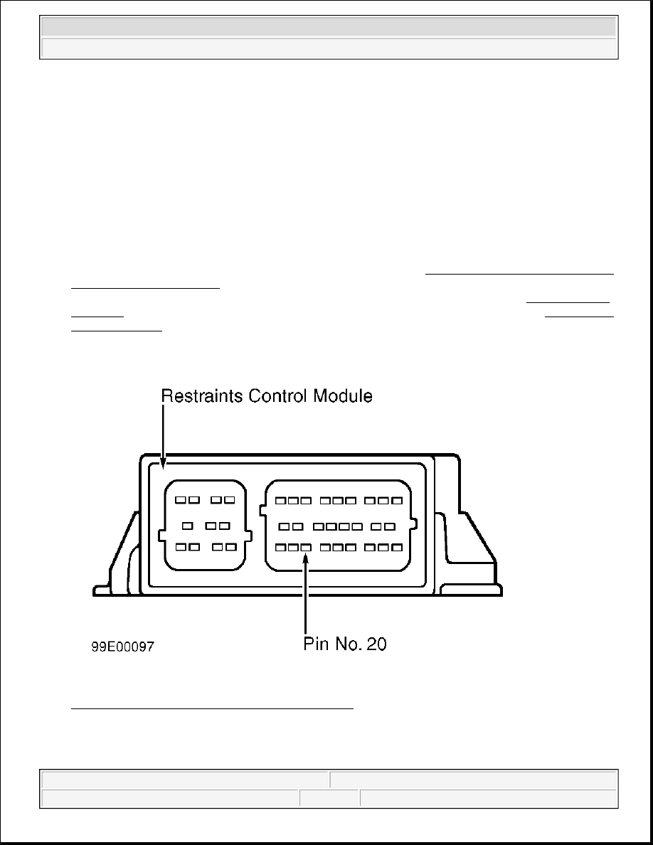
Fig. 17: Identifying Restraints Control Module Pins 
Courtesy of FORD MOTOR CO. 

TEST C: AIR BAG WARNING LIGHT SHORT TO BATTERY VOLTAGE (DTC B1870) 


2003 Ford Pickup F150 

2003 ACCESSORIES/SAFETY EQUIPMENT Air Bag Restraint Systems - F150 Pickup


Description 

AIR BAG warning light is designed to illuminate for 6 seconds when ignition switch is turned to RUN position. 
The initial 6 second illumination is normal and is call prove-out. The AIR BAG warning light is then used to 
warn vehicle operator that there is a fault in the air bag system. 

Restraint Control Module (RCM) monitors AIR BAG warning light for short to battery voltage conditions. If 
RCM detects short to battery voltage in AIR BAG warning light circuit, it will store Diagnostic Trouble Code 
(DTC) 1870 in memory. In RCM detects AIR BAG warning light failure in addition to another air bag system 
failure, it will send signal to Generic Electronic Module (GEM) to produce 5 sets of 5 tone bursts. 

Possible Causes 

AIR BAG warning light inoperative condition could be caused by damaged Black/Yellow wire, instrument 
cluster malfunction or faulty RCM. 

1. Check for hard or intermittent DTC 

 
Turn ignition switch to OFF position. Connect scan tool to Data Link Connector (DLC). See USING 
SCAN TOOL
 under DIAGNOSTICS. Turn ignition switch to RUN position. Retrieve and record any 
continuous DTCs. See RETRIEVING FAULT CODES under DIAGNOSTICS. Perform on-demand 
self-test. See ON-DEMAND SELF-TEST under DIAGNOSTICS. If DTC B1870 was retrieved during 
on-demand self-test, fault is hard. Go to next step. If DTC B1870 was not retrieved, fault is intermittent. 
Go to step 3 . 

2. Check AIR BAG warning light circuit 

 
Turn ignition switch to OFF position. Disable air bag system. See DISABLING SYSTEM under 
DISABLING & ACTIVATING AIR BAG SYSTEM. Access RCM and disconnect harness connector. 
See RESTRAINTS CONTROL MODULE (RCM) under REMOVAL & INSTALLATION. Turn 
ignition switch to RUN position. If AIR BAG warning light illuminates, replace RCM. Go to step 4 . If 
AIR BAG warning light does not illuminate, access and check AIR BAG warning light bulb. See 
INSTRUMENT CLUSTER under REMOVAL & INSTALLATION. If AIR BAG warning light bulb is 
okay, repair short to battery voltage in Black/Yellow wire (circuit No. 608). See WIRING 
DIAGRAMS
 . Go to step 4 . 

3. Check for intermittent fault 

 
Refer to continuous DTCs recorded in step 1 . If DTC retrieved in step 1 was an intermittent fault, check 
for cause of intermittent short to battery in Black/Yellow wire (circuit No. 608). See WIRING 
DIAGRAMS
 . Attempt to recreate fault by flexing wire harness and cycling ignition switch frequently. 
Repair any intermittent problems found. Go to next step. If DTC retrieved in step 1 was not an 
intermittent fault. Go to next step. 

4. Check for additional DTCs 

NOTE:

Before proceeding, see AIR BAG SAFETY PRECAUTIONS .


2003 Ford Pickup F150 

2003 ACCESSORIES/SAFETY EQUIPMENT Air Bag Restraint Systems - F150 Pickup


Refer to continuous DTCs recorded in step 1 . If any continuous DTCs were retrieved, go to diagnostic 
trouble code identification table for direction to appropriate test. See DIAGNOSTIC TROUBLE CODE 
(DTC) IDENTIFICATION
 table. DO NOT clear any DTCs until all DTCs have been resolved. If no 
continuous DTCs were retrieved, reconnect air bag system. Activate air bag system. See ACTIVATING 
SYSTEM
 under DISABLING & ACTIVATING AIR BAG SYSTEM. Clear all DTCs. See CLEARING 
FAULT CODES
 under DIAGNOSTICS.  

TEST D: PASSENGER AIR BAG DEACTIVATION (PAD) SWITCH FAULT (DTC B1871) 

Description 

Restraints Control Module (RCM) monitors status of Passenger Air Bag Deactivation (PAD) switch at terminal 
No. 8 (White/Light Blue wire). PAD switch signals RCM by switching resistance to ground. If RCM senses 
900-1100 ohms in PAD switch, it enables passenger-side air bag and turns off PAD switch warning light. If 
RCM senses 400-600 ohms in PAD switch, it deactivates passenger-side air bag and turns on PAD switch 
warning light. If RCM senses an invalid resistance, it will store Diagnostic Trouble Code (DTC) B1871 in 
memory and flash Code 25 on AIR BAG warning light. 

Possible Causes 

An PAD switch fault could be caused by damaged or inoperative PAD switch, damaged or inoperative RCM, a 
short to battery, short to ground or open in White/Light Blue wire. 

1. Check for hard or intermittent DTC 

 
Turn ignition switch to OFF position. Connect scan tool to Data Link Connector (DLC). See USING 
SCAN TOOL
 under DIAGNOSTICS. Turn ignition switch to RUN position. Retrieve and record any 
continuous DTCs. See RETRIEVING FAULT CODES under DIAGNOSTICS. Perform on-demand 
self-test. See ON-DEMAND SELF-TEST under DIAGNOSTICS. If DTC B1871 was retrieved during 
on-demand self-test, fault is hard. Go to next step. If DTC B1871 was not retrieved, fault is intermittent. 
Go to step 6 . 

2. Check PAD switch ON position 

 
Turn ignition switch to OFF position. Disable air bag system. See DISABLING SYSTEM under 
DISABLING & ACTIVATING AIR BAG SYSTEM. Access RCM and disconnect harness connector. 
See RESTRAINTS CONTROL MODULE (RCM) under REMOVAL & INSTALLATION. Turn PAD 
switch to ON position. Measure resistance between harness side of RCM connector terminals No. 8 
(White/Light Blue wire, circuit No. 1112) and No. 21 (Black/Orange wire, circuit No. 649). See Fig. 14 . 
If resistance is 900-1100 ohms, go to next step. If resistance is not 900-1100 ohms, go to step 4 . 

3. Check PAD switch OFF position 

 
Turn PAD switch to OFF position. Measure resistance between harness side of RCM connector terminals 

NOTE:

Before proceeding, see AIR BAG SAFETY PRECAUTIONS .


2003 Ford Pickup F150 

2003 ACCESSORIES/SAFETY EQUIPMENT Air Bag Restraint Systems - F150 Pickup


No. 8 (White/Light Blue wire) and No. 21 (Black/Orange wire). If resistance is 400-600 ohms, replace 
RCM. Go to step 7 . If resistance is not 400-600 ohms, go to next step. 

4. Check circuit for short to battery 

 
Turn ignition switch to RUN position. Measure voltage between harness side of RCM connector terminal 
No. 8 (White/Light Blue wire) and terminals No. 21 (Black/Orange wire) and No. 2 (Violet/Orange wire, 
circuit No. 298) independently. If voltage is less than 0.2 volt, go to next step. If voltage is more than 0.2 
volt, repair short to battery in White/Light Blue wire. See WIRING DIAGRAMS . Go to step 7 . 

5. Check circuit for open 

 
Turn ignition switch to OFF position. Access PAD switch and disconnect connector. See PASSENGER-
SIDE AIR BAG DEACTIVATE SWITCH (PAD)
 under REMOVAL & INSTALLATION. Measure 
resistance of White/Light Blue wire between harness side of RCM connector terminal No. 8 and harness 
side of PAD switch connector. If resistance is less than 10 ohms, replace PAD switch. Go to step 7 . If 
resistance is more than 10 ohms, repair open in White/Light Blue wire. Go to step 7 . 

6. Check for intermittent fault 

 
Refer to continuous DTCs recorded in step 1 . If DTC retrieved in step 1 was an intermittent fault, check 
for cause of intermittent faults in White/Light Blue wire (circuit No. 1112). See WIRING DIAGRAMS 
Attempt to recreate fault by flexing wire harness and cycling ignition switch frequently. Repair any 
intermittent problems found. Go to next step. If DTC retrieved in step 1 was not an intermittent fault. Go 
to next step. 

7. Check for additional DTCs 

 
Refer to continuous DTCs recorded in step 1 . If any continuous DTCs were retrieved, go to diagnostic 
trouble code identification table for direction to appropriate test. See DIAGNOSTIC TROUBLE CODE 
(DTC) IDENTIFICATION
 table. DO NOT clear any DTCs until all DTCs have been resolved. If no 
continuous DTCs were retrieved, reconnect air bag system. Activate air bag system. See ACTIVATING 
SYSTEM
 under DISABLING & ACTIVATING AIR BAG SYSTEM. Clear all DTCs. See CLEARING 
FAULT CODES
 under DIAGNOSTICS.  

TEST E: LEFT PRETENSIONER CIRCUIT RESISTANCE HIGH OR LOW (DTC B1877 OR B1885) 

Description 

Restraints Control Module (RCM) monitors resistance of circuits to left seat belt pretensioner. When RCM 

NOTE:

Before proceeding, see AIR BAG SAFETY PRECAUTIONS . 
Diagnostic tests or repairs are not to be performed on seat belt pretensioner 
system with front seats installed in vehicle. Prior to diagnosis or repair of 
pretensioner system, remove front seats and ensure appropriate pretensioner 
simulators are installed at pretensioner connectors. See FRONT SEAT under 
REMOVAL & INSTALLATION.


2003 Ford Pickup F150 

2003 ACCESSORIES/SAFETY EQUIPMENT Air Bag Restraint Systems - F150 Pickup


Content   ..  1724  1725  1726  1727   ..