Fiat Freemont (2016 year). Manual - part 7


  Index      Fiat     Fiat Freemont (2016 year) - manual in english


Search            


Content      ..     5      6      7      8     ..


Fiat Freemont (2016 year). Manual - part 7


ILLUMINATED ENTRY

The courtesy lights will turn on when you use the
Remote Keyless Entry (RKE) transmitter to unlock the
doors or open any door or liftgate.

This feature also turns on the approach lighting in the
outside mirrors (for versions/markets, where pro-
vided). Refer to “Mirrors” in “Knowing Your Vehicle”
for further information.

The interior lights will fade to off after approximately
30 seconds or they will immediately fade to off once
the ignition is cycled to the ON/RUN position from the
OFF position.

NOTE:

• The front courtesy overhead console and door cour-

tesy lights will turn on if the dimmer control is in the
"Dome ON" position (extreme top position).

• The Illuminated Entry system will not operate if the

dimmer control is in the “Dome defeat” position
(extreme bottom position).

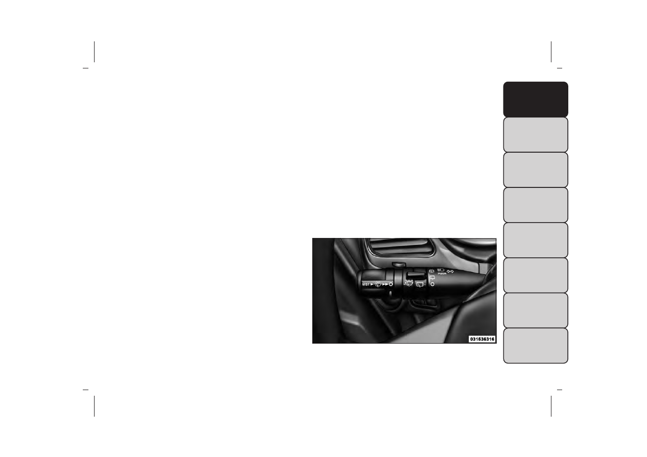
WINDSHIELD WIPERS AND
WASHERS

The windshield wiper/washer control lever is located
on the left side of the steering column.

(fig. 62)

The front wipers are operated by rotating a switch,
located at the end of the lever. Refer to “Rear Window
Features” for further information on using the rear
window wiper/washer.

(fig. 62)

Windshield Wiper/Washer Lever

97

-------------------------------------------------------------------------------------------------------------------------------------------------------------

INTERMITTENT WIPER SYSTEM

Use the intermittent wiper system when weather con-
ditions make a single wiping cycle, with a variable pause
between cycles, desirable. Rotate the end of the wind-
shield wiper/washer control lever to one of the first
five detents to select the desired delay interval

(fig. 63)

There are five delay settings, which allow you to regu-
late the wipe interval from a minimum of one cycle
every two seconds to a maximum of approximately 36
seconds between cycles at vehicle speeds below
16 km/h. At speeds greater than 16 km/h, the delay
varies from a minimum of one cycle every second to a
maximum of approximately 18 seconds between
cycles.

NOTE: The wiper delay times depend on vehicle
speed. If the vehicle is moving less than 16 km/h, delay
times will be doubled.

WINDSHIELD WIPER OPERATION

Rotate the end of the lever upward, to the first detent
past the intermittent settings for low-speed wiper
operation. Rotate the end of the lever upward to the
second detent past the intermittent settings for high-
speed wiper operation.

(fig. 64)

(fig. 63)

Front Wiper Control

(fig. 64)

Front Wiper Control

98

-------------------------------------------------------------------------------------------------------------------------------------------------------------

NOTE: The wipers will automatically return to the
“park” position if you turn OFF the ignition switch
while they are operating. The wipers will resume op-
eration when you turn the ignition switch back to the
ON position.

• Turn the windshield wipers OFF when
driving through an automatic car wash.
Damage to the windshield wipers may

result if the wiper control is left in any position
other than OFF.
• In cold weather, always turn OFF the wiper
switch and allow the wipers to return to the park
position before turning OFF the engine. If the
wiper switch is left ON and the wipers freeze to
the windshield, damage to the wiper motor may
occur when the vehicle is restarted.
• Always remove any buildup of snow that pre-
vents the windshield wiper blades from returning
to the “park” position. If the windshield wiper
control is turned OFF, and the blades cannot
return to the“park”position,damage to the wiper
motor may occur.

WINDSHIELD WASHERS

To use the windshield washer, push the washer knob,
located on the end of the multifunction lever, inward to
the second detent.

If you activate the washer while the wiper control is in
the delay range, the wipers will operate in low-speed
for two or three wipe cycles after releasing the lever
and then resume the intermittent interval previously
selected.

If you activate the washer while the wiper control is in
the OFF position, the wipers will operate for two or
three wipe cycles and then turn OFF.

WARNING!

Sudden loss of visibility through the
windshield could lead to a collision.You

might not see other vehicles or other obstacles.To
avoid sudden icing of the windshield during freez-
ing weather, warm the windshield with the de-
froster before and during windshield washer use.

99

-------------------------------------------------------------------------------------------------------------------------------------------------------------

MIST FEATURE

Push the washer knob, located on the end of the
multifunction lever, inward to the first detent to acti-
vate a single wipe cycle to clear the windshield of road
mist or spray from a passing vehicle. The wipers will
continue to operate until you release the lever.

NOTE: The mist feature does not activate the washer
pump; therefore, no washer fluid will be sprayed on the
windshield. The wash function must be used in order to
spray the windshield with washer fluid.

HEADLIGHTS ON WITH WIPERS (for
versions/markets, where provided)

When this feature is active, the headlights will turn on
after the wipers are turned on if the headlight switch is
placed in the AUTO position and programmable fea-
ture is set to ON. In addition, the headlights will turn
off when the wipers are turned off if they were turned
on by this feature.

NOTE: The Headlights On with Wipers feature can be
turned on or off using the Uconnect® System. Refer to
“Uconnect® Settings” in “Knowing Your Vehicle” for
further information.

HEADLIGHT WASHERS (for
versions/markets, where
provided)

The Headlight Washers are recessed into the top of
the fascia, centrally located below each headlight.

The windshield wiper/washer control lever operates
the headlight washers when the ignition switch is in the
ON position and the headlights are ON. The lever is
located on the left side of the steering column.

To use the headlight washers, push the washer knob,
located on the end of the multifunction lever, inward to
the second detent to activate the windshield washers
and release it. When this is done, the two stationary
washer nozzles at each headlight spray one timed
high-pressure spray of washer fluid onto each headlight
lens. In addition, the windshield washers will spray the
windshield and the windshield wipers will cycle.

NOTE: After turning the ignition switch and head-
lights ON, the headlight washers will operate on the
first spray of the windshield washer and then every
eleventh spray after that.

100

-------------------------------------------------------------------------------------------------------------------------------------------------------------

REAR WINDOW FEATURES

REAR WINDOW WIPER/WASHER

The rear window wiper/washer control is located on
the left side of the steering column.

(fig. 65)

Rotate the switch upward to the first detent
position for rear wiper operation.

NOTE: The rear wiper operates in an intermittent
mode only.

Rotate the switch upward past the first detent
position to activate the rear washer. The washer

pump will continue to operate as long as the switch is
held. Upon release, the wiper will cycle three times
before returning to the set position.

(fig. 66)

If the rear wiper is operating when the ignition is
turned to the LOCK position, the wiper will automati-
cally return to the “Park” position. When the vehicle is
restarted, the wiper will resume function at whichever
position the switch is set at.

(fig. 65)

Rear Wiper/Washer

(fig. 66)

Rear Wiper/Washer Control

101

-------------------------------------------------------------------------------------------------------------------------------------------------------------

• Turn the rear wiper off when driving
through an automatic car wash. Damage
to the rear wiper may result if the rear

wiper switch is left in the ON position.
• In cold weather, always turn off the rear wiper
switch and allow the rear wiper to return to the
park position before turning off the engine. If the
rear wiper switch is left on and the rear wiper
freezes to the window, damage to the rear wiper
motor may occur when the vehicle is restarted.
• Always remove any buildup of snow that pre-
vents the rear wiper blade from returning to the
park position. If the rear wiper control is turned
off and the blade cannot return to the park
position, damage to the rear wiper motor may
occur.

REAR WINDOW DEFROSTER

The rear window defroster button is located on
the climate control panel. Press this button to

turn on the rear window defroster and the heated
outside mirrors (for versions/markets, where pro-
vided). An indicator in the button will illuminate when
the rear window defroster is on. The rear window
defroster automatically turns off after approximately
10 minutes.

NOTE: To prevent excessive battery drain, use the
rear window defroster only when the engine is oper-
ating.

Failure to follow these cautions can
cause damage to the heating elements:
• Use care when washing the inside of

the rear window. Do not use abrasive window
cleaners on the interior surface of the window.
Use a soft cloth and a mild washing solution,
wiping parallel to the heating elements. Labels
can be peeled off after soaking with warm water.
• Do not use scrapers, sharp instruments, or abra-
sive window cleaners on the interior surface of
the window.
• Keep all objects a safe distance from the win-
dow.

102

-------------------------------------------------------------------------------------------------------------------------------------------------------------

ELECTRONIC SPEED CONTROL

When engaged, the Electronic Speed Control takes
over accelerator operations at speeds greater than
40 km/h.

(fig. 67)

NOTE: In order to ensure proper operation, the
Electronic Speed Control System has been designed to
shut down if multiple Speed Control functions are
operated at the same time. If this occurs, the Electronic
Speed Control System can be reactivated by pushing
the Electronic Speed Control ON/OFF button and
resetting the desired vehicle set speed.

TO ACTIVATE

Push the ON/OFF button. The Cruise Indicator Light
in the instrument cluster will illuminate. To turn the
system off, push the ON/OFF button a second time.
The Cruise Indicator Light will turn off. The system
should be turned off when not in use.

WARNING!

Leaving the Electronic Speed Control
system on when not in use is dangerous.

You could accidentally set the system or cause it
to go faster than you want.You could lose control
and have an accident. Always leave the system
OFF when you are not using it.

TO SET A DESIRED SPEED

Turn the Electronic Speed Control ON. When the
vehicle has reached the desired speed, press the SET (-)
button and release. Release the accelerator and the
vehicle will operate at the selected speed.

NOTE: The vehicle should be traveling at a steady
speed and on level ground before pressing the SET (-)
button.

(fig. 67)

Electronic Speed Control Buttons

1 — ON/OFF

3 — SET -

2 — RES +

4 — CANCEL

103

-------------------------------------------------------------------------------------------------------------------------------------------------------------

TO DEACTIVATE

A soft tap on the brake pedal, pushing the CANCEL
button, or normal brake pressure while slowing the
vehicle will deactivate the Electronic Speed Control
without erasing the set speed memory.

Pressing the ON/OFF button or turning the ignition
switch OFF erases the set speed memory.

TO RESUME SPEED

To resume a previously set speed, push the RES (+)
button and release. Resume can be used at any speed
above 32 km/h.

TO VARY THE SPEED SETTING

To Increase Speed

When the Electronic Speed Control is set, you can
increase speed by pushing the RES (+) button.

• Pressing the RES (+) button once will result in a

2 km/h increase in set speed. Each subsequent tap of
the button results in an increase of 2 km/h.

• If the button is continually pressed, the set speed will

continue to increase until the button is released,
then the new set speed will be established.

To Decrease Speed

When the Electronic Speed Control is set, you can
decrease speed by pushing the SET (-) button.

• Pressing the SET (-) button once will result in a

2 km/h decrease in set speed. Each subsequent tap of
the button results in a decrease of 2 km/h.

• If the button is continually pressed, the set speed will

continue to decrease until the button is released,
then the new set speed will be established.

TO ACCELERATE FOR PASSING

Press the accelerator as you would normally. When the
pedal is released, the vehicle will return to the set
speed.

104

-------------------------------------------------------------------------------------------------------------------------------------------------------------

Using Electronic Speed Control On Hills

The transmission may downshift on hills to maintain
the vehicle set speed.

NOTE: The Electronic Speed Control system main-
tains speed up and down hills. A slight speed change on
moderate hills is normal.

On steep hills, a greater speed loss or gain may occur
so it may be preferable to drive without Electronic
Speed Control.

WARNING!

Electronic Speed Control can be danger-
ous where the system cannot maintain a

constant speed.Your vehicle could go too fast for
the conditions, and you could lose control and
have an accident. Do not use Electronic Speed
Control in heavy traffic or on roads that are
winding, icy, snow-covered or slippery.

OVERHEAD CONSOLE

The overhead console contains courtesy/reading lights,
storage for sunglasses, an interior observation mirror
and an optional power sunroof switch.

(fig. 68)

(fig. 68)

Overhead Console

105

-------------------------------------------------------------------------------------------------------------------------------------------------------------

COURTESY/READING LIGHTS

The overhead console has two courtesy lights. The
lights turn on when a door or the liftgate is opened. If
your vehicle is equipped with Remote Keyless Entry
(RKE) the lights will also turn on when the UNLOCK
button on the RKE transmitter is pressed. The cour-
tesy lights also function as reading lights. Press in on
each lens to turn these lights on while inside the
vehicle. Press the lens a second time to turn each light
off. You may adjust the direction of these lights by
pressing the outside ring, which is identified with four
directional arrows.

(fig. 69)

SUNGLASSES STORAGE

To access the storage compartment, press on the
raised bars on the compartment door in the center of
the console and release and the door will swing
downward.

(fig. 70)

INTERIOR OBSERVATION MIRROR

The convex interior observation mirror provides the
driver and front seat passenger a wide field of view to
conveniently view passengers sitting in the rear passen-
ger seats. To use the interior observation mirror, press
on the raised bars on the compartment door and
release (the door will swing downward), then raise the
door until it is almost closed and release. The door will
latch in position to use the interior observation mirror.

(fig. 69)

Courtesy/Reading Light

(fig. 70)

Sunglasses Storage Compartment

106

-------------------------------------------------------------------------------------------------------------------------------------------------------------

NOTE: From the “observation mirror” position, the
door can only be closed.

To return to the full open position, the door must first
be closed and then opened by pressing the latch again
to release.

(fig. 71)

POWER SUNROOF SWITCH (for
versions/markets, where provided)

Refer to “Power Sunroof” for further information.

HAZARD WARNING FLASHERS

The Hazard Warning flasher switch is located in the
instrument panel switch bank, above the climate
controls.

Press the switch to turn on the Hazard Warning
flasher. When the switch is activated, all direc-

tional turn signals will flash on and off to warn oncom-
ing traffic of an emergency. Press the switch a second
time to turn off the Hazard Warning flashers.

This is an emergency warning system and it should not
be used when the vehicle is in motion. Use it when your
vehicle is disabled and it is creating a safety hazard for
other motorists.

When you must leave the vehicle to seek assistance,
the Hazard Warning flashers will continue to operate
even though the ignition is placed in the OFF position.

NOTE: With extended use the Hazard Warning flash-
ers may wear down your battery.

(fig. 71)

Observation Mirror

107

-------------------------------------------------------------------------------------------------------------------------------------------------------------

STORAGE

GLOVE COMPARTMENT

The glove compartment is located on the passenger
side of the instrument panel. Pull on the release handle
to open the glove compartment.

(fig. 72)

FLOOR CONSOLE STORAGE

An open storage area, or cubby bin, is located in the
floor console.

(fig. 73)

CENTER CONSOLE STORAGE

There is a storage tray and storage compartment
located under the center console armrest.

(fig. 74)

(fig. 72)

Glove Compartment

(fig. 73)

Floor Console Cubby Bin

(fig. 74)

Center Console

108

-------------------------------------------------------------------------------------------------------------------------------------------------------------

Pull upward on the release handle, located on the front
of the lid, to gain access to the storage tray and storage
compartment.

(fig. 75)

The storage tray can be slid forward and rearward or
removed to access the center console storage
compartment.

(fig. 76)

WARNING!

Do not operate this vehicle with a con-
sole compartment lid in the open posi-

tion. Driving with the console compartment lid
open may result in injury in a collision.

(fig. 75)

Center Console Storage Tray

(fig. 76)

Center Console Storage Compartment

109

-------------------------------------------------------------------------------------------------------------------------------------------------------------

Sliding Armrest (for automatic transmission
only)

The center console armrest can also be slid rearward
for easy access to the storage area.

(fig. 77)

FLIP 'N STOW™ FRONT PASSENGER SEAT
STORAGE (for versions/markets, where
provided)

The seat latch release-loop is located in the center of
the seat cushion between the seat cushion and the
seatback. Pull the loop upward to release the latch and
then forward to open the seat to the detent position.

(fig. 78)

NOTE: Make sure that objects inside the bin do not
interfere with the latch before closing the seat. Push
the seat cushion downward after closing it to make
sure it latches to the base.

WARNING!

Be certain that the seat cushion is
locked securely into position before us-

ing the seat. Otherwise, the seat will not provide
the proper stability for passengers. An improp-
erly latched seat cushion could cause serious
injury.

(fig. 77)

Sliding Armrest

(fig. 78)

Front Passenger Seat Storage Compartment

110

-------------------------------------------------------------------------------------------------------------------------------------------------------------

SECOND-ROW PASSENGER SEAT
TEMPORARY STORAGE BIN

This is a temporary storage bin designed for use when
the seatback/armrest is down. Be sure to remove all
items from this bin before raising the seatback/armrest.

SECOND-ROW MAP POCKET AND
GROCERY RETAINERS

A map storage pocket and grocery retainers are lo-
cated on the back of the drivers seatback.

(fig. 79)

IN-FLOOR STORAGE BIN WITH
REMOVABLE LINER

NOTE: Position the front seat to at least a mid-track
position to provide easier access to the storage bin.

An in-floor storage bin is located behind each front
seat. Each 5.9L bin can hold up to 12, 0.35L cans, plus
ice, or other items. The removable bin liner allows for
easy filling, emptying, and cleaning.

To access the bin, position the floor mat aside (for
versions/markets, where provided). Pull the door latch
release-loop upward to release the latch and then
forward to open the bin door.

(fig. 80)

(fig. 79)

Seat Storage And Grocery Retainers

(fig. 80)

In-Floor Storage

111

-------------------------------------------------------------------------------------------------------------------------------------------------------------

The liner can be removed for easy cleaning.

(fig. 81)

ELECTRICAL POWER OUTLETS

A 12 Volt (13 Amp) power outlet is located in the
center console below the radio. The power outlet has
power available when the ignition switch in the ON/
RUN or ACC position.

(fig. 82)

This power outlet will also operate a conventional cigar
lighter unit. To preserve the heating element, do
not hold the lighter in the heating position.

(fig. 81)

Removable Liner

(fig. 82)

Front 12 Volt Power Outlet

112

-------------------------------------------------------------------------------------------------------------------------------------------------------------


Content      ..     5      6      7      8     ..