Dodge Diesel (2004 year). Manual - part 9


  Index      Dodge     Dodge Diesel (2004 year) - manual in english


Search            copyright infringement  


Content      ..     7      8      9      10     ..


Dodge Diesel (2004 year). Manual - part 9


2. Grasp the knob on the load floor and lift the knob until
the load floor unfolds into position.

3. Reverse the procedure to store the load floor.

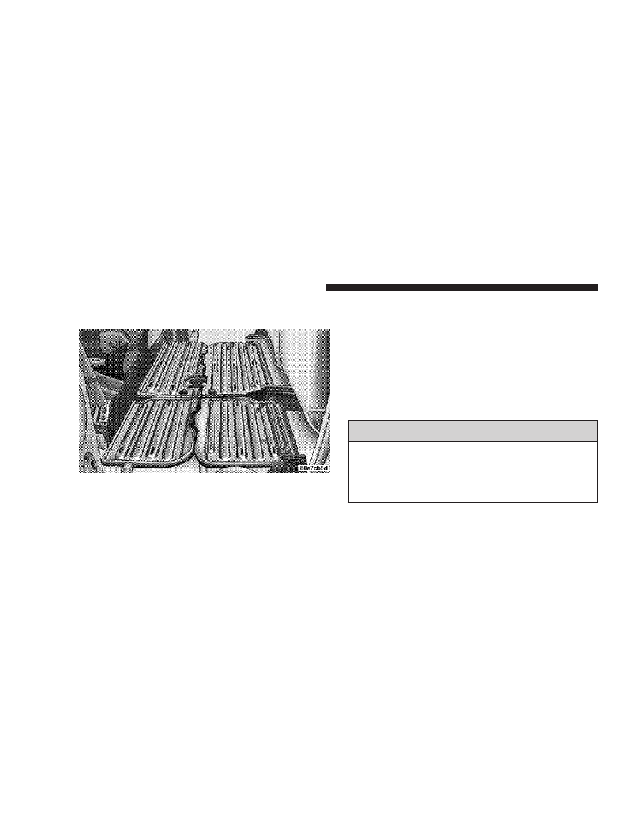
Positioning the Load Floor for Storage Access Under
the Seat

1. Lift the 60/40 seat cushion(s) to the upward position.

2. Unsnap the securing snap located at either side of the
load floor.

3. Lift the load floor up to access storage under the load
floor.

WARNING!

Do not drive with the load floor in the up position.
When stopping fast or in an accident, the load floor
could move to the down position causing serious
injury.

132

UNDERSTANDING THE FEATURES OF YOUR VEHICLE

4. Reverse the procedure to put the load floor back in the
secured down position before you operate the vehicle.

PICKUP BOX

The pickup box on your new Ram has many features
designed for utility and convenience.

NOTE:

If you are installing a toolbox to the front of the

pickup box, you must use Mopar

t toolbox brackets

available from you dealer.

UNDERSTANDING THE FEATURES OF YOUR VEHICLE

133

3

You can carry wide building materials (sheets of ply-
wood, etc.) by building a raised load floor. Place lumber
across the box in the indentations provided above the
wheel housings and in the bulkhead dividers to form the
floor.

WARNING!

The pickup box is intended for load carrying pur-
poses only, not for passengers, who should sit in
seats and use seat belts.

WARNING!

• Care should always be exercised when operating a

vehicle with unrestrained cargo. Vehicle speeds
may need to be reduced. Severe turns or rough
roads may cause shifting or bouncing of the cargo
that may result in vehicle damage. If wide build-
ing materials are to be frequently carried, the
installation of a support is recommended. This
will restrain the cargo and transfer the load to the
pickup box floor.

• If you wish to carry more than 600 lbs (272 kg) of

material suspended above the wheelhouse, sup-
ports must be installed to transfer the weight of
the load to the pickup box floor or vehicle damage
may result. The use of proper supports will permit
loading up to the rated payload.

• Unrestrained cargo may be thrown forward in an

accident causing serious or fatal injury.

134

UNDERSTANDING THE FEATURES OF YOUR VEHICLE

There are stampings in the sheet metal on the inner side
bulkheads of the box in front of and behind both wheel
housings. Place wooden boards across the box from side
to side to create separate load compartments in the
pickup box.

There are four tie-down cleats bolted to the lower sides of
the pickup box that can sustain loads up to 1000 lbs (450
kg) total.

SLIDE-IN CAMPERS

Camper Applications

Certain truck models are not recommended for slide-in
campers. To determine if your vehicle is excluded, please
refer to the “Consumer Information Truck-Camper Load-
ing” document available from your dealer. For safety
reasons, follow all instructions in this important docu-
ment.

NOTE:

When a cap or pickup camper is installed on a

vehicle, an alternate CHMSL (Center High Mounted Stop
Light) must be provided.

EASY-OFF TAILGATE

To simplify mounting of a camper unit with an overhang,
the tailgate can be removed quickly. If the truck is a 3500
dual rear wheel model, unplug the tailgate wire harness
from under the rear of the truck and pull the harness out
of the cargo box access hole. Unlatch the tailgate and
remove the support cables by releasing the lock tang
from the pivot, then rotate and pull away from the box.
Once the cables are free, move to the right side of the
tailgate hinge bracket.

Raise the right side of the tailgate until the right side
pivot clears the hanger bracket. Slide the entire tailgate to
the right to free the left side pivot. Remove the tailgate
from the vehicle entirely. Do not carry the tailgate loose in
the truck pickup box.

UNDERSTANDING THE FEATURES OF YOUR VEHICLE

135

3

NOTE:

Dual rear wheel pickup models require properly

spaced rear clearance lights. If such a vehicle is operated
without a tailgate, suitable lights must be installed.

WARNING!

To avoid inhaling carbon monoxide, which is deadly,
the exhaust system on vehicles equipped with “Cap
or Slide-In Campers” should extend beyond the over-
hanging camper compartment and be free of leaks.

136

UNDERSTANDING THE FEATURES OF YOUR VEHICLE

UNDERSTANDING YOUR INSTRUMENT PANEL

CONTENTS

m Instruments And Controls . . . . . . . . . . . . . . . . . 141
m Instrument Cluster . . . . . . . . . . . . . . . . . . . . . . 142
m Instrument Cluster Description . . . . . . . . . . . . . 143
m Electronic Digital Clock . . . . . . . . . . . . . . . . . . 151

▫ Clock Setting Procedure . . . . . . . . . . . . . . . . . 151

m Sales Code RBB—AM/FM Stereo Radio With

Cassette Tape Player And CD Changer
Capability . . . . . . . . . . . . . . . . . . . . . . . . . . . . 152

▫ Operating Instructions . . . . . . . . . . . . . . . . . . 152
▫ Power Button . . . . . . . . . . . . . . . . . . . . . . . . 152

▫ Electronic Volume Control . . . . . . . . . . . . . . . 152
▫ Seek . . . . . . . . . . . . . . . . . . . . . . . . . . . . . . 153
▫ Tune . . . . . . . . . . . . . . . . . . . . . . . . . . . . . . 153
▫ To Set The Push-Button Memory . . . . . . . . . . 153
▫ Balance . . . . . . . . . . . . . . . . . . . . . . . . . . . . 154
▫ Fade . . . . . . . . . . . . . . . . . . . . . . . . . . . . . . 154
▫ Bass And Treble Tone Control . . . . . . . . . . . . 154
▫ AM/FM Selection . . . . . . . . . . . . . . . . . . . . . 154
▫ Mode Button . . . . . . . . . . . . . . . . . . . . . . . . 154

4

▫ Cassette Player Features . . . . . . . . . . . . . . . . 154
▫ CD Changer Control Capability — If

Equipped . . . . . . . . . . . . . . . . . . . . . . . . . . . 156

▫ Radio Display Messages . . . . . . . . . . . . . . . . 157

m Sales Code RAZ—AM/ FM Stereo Radio With

Cassette Tape Player, CD Player And CD
Changer Controls — If Equipped . . . . . . . . . . . 158

▫ Operating Instructions — Radio . . . . . . . . . . . 158
▫ Power Switch, Volume Control . . . . . . . . . . . . 159
▫ Seek Button (Radio Mode) . . . . . . . . . . . . . . . 159
▫ Tuning . . . . . . . . . . . . . . . . . . . . . . . . . . . . . 159
▫ PTY (Program Type) Button . . . . . . . . . . . . . . 159
▫ Balance . . . . . . . . . . . . . . . . . . . . . . . . . . . . 161
▫ Fade . . . . . . . . . . . . . . . . . . . . . . . . . . . . . . 161

▫ Tone Control . . . . . . . . . . . . . . . . . . . . . . . . 161
▫ AM/FM Selection . . . . . . . . . . . . . . . . . . . . . 161
▫ Scan Button . . . . . . . . . . . . . . . . . . . . . . . . . 161
▫ To Set The Radio Push-Button Memory . . . . . . 162
▫ To Change From Clock To Radio Mode . . . . . . 162
▫ Operating Instructions — Tape Player . . . . . . . 162
▫ Seek Button . . . . . . . . . . . . . . . . . . . . . . . . . 162
▫ Fast Forward (FF) . . . . . . . . . . . . . . . . . . . . . 163
▫ Rewind (RW) . . . . . . . . . . . . . . . . . . . . . . . . 163
▫ Tape Eject . . . . . . . . . . . . . . . . . . . . . . . . . . . 163
▫ Scan Button . . . . . . . . . . . . . . . . . . . . . . . . . 163
▫ Changing Tape Direction . . . . . . . . . . . . . . . . 163
▫ Metal Tape Selection . . . . . . . . . . . . . . . . . . . 163

138

UNDERSTANDING YOUR INSTRUMENT PANEL

▫ Pinch Roller Release . . . . . . . . . . . . . . . . . . . 164
▫ Noise Reduction . . . . . . . . . . . . . . . . . . . . . . 164
▫ Operating Instructions — CD Player . . . . . . . . 164
▫ Inserting The Compact Disc . . . . . . . . . . . . . . 164
▫ Seek Button . . . . . . . . . . . . . . . . . . . . . . . . . 165
▫ EJT CD (Eject) Button . . . . . . . . . . . . . . . . . . 165
▫ FF/Tune/RW . . . . . . . . . . . . . . . . . . . . . . . . 166
▫ Program Button 4 (Random Play) . . . . . . . . . . 166
▫ Mode . . . . . . . . . . . . . . . . . . . . . . . . . . . . . . 166
▫ Tape CD Button . . . . . . . . . . . . . . . . . . . . . . 166
▫ Time Button . . . . . . . . . . . . . . . . . . . . . . . . . 167
▫ Scan Button . . . . . . . . . . . . . . . . . . . . . . . . . 167

▫ CD Changer Control Capability — If

Equipped . . . . . . . . . . . . . . . . . . . . . . . . . . . 167

m Sales Code RBK—AM/ FM Stereo Radio With

CD Player And CD Changer Controls . . . . . . . . 168

▫ Radio Operation . . . . . . . . . . . . . . . . . . . . . . 168
▫ CD Player Operation . . . . . . . . . . . . . . . . . . . 171
▫ CD Changer Control Capability — If

Equipped . . . . . . . . . . . . . . . . . . . . . . . . . . . 172

▫ Radio Display Messages . . . . . . . . . . . . . . . . 174

m Sales Code RBQ—AM/FM Stereo Radio With

6 - Disc CD Changer . . . . . . . . . . . . . . . . . . . . 175

▫ Radio Operation . . . . . . . . . . . . . . . . . . . . . . 175
▫ CD Player Operation . . . . . . . . . . . . . . . . . . . 177

UNDERSTANDING YOUR INSTRUMENT PANEL

139

4

m Remote Sound System Controls — If Equipped . . 181

▫ Radio Operation . . . . . . . . . . . . . . . . . . . . . . 182
▫ Tape Player . . . . . . . . . . . . . . . . . . . . . . . . . 182
▫ CD Player . . . . . . . . . . . . . . . . . . . . . . . . . . 182

m Cassette Tape And Player Maintenance . . . . . . . 183
m Compact Disc Maintenance . . . . . . . . . . . . . . . . 184
m Radio Operation And Cellular Phones . . . . . . . . 184
m Climate Controls . . . . . . . . . . . . . . . . . . . . . . . 185

▫ Heater Only — Fleet Vehicles . . . . . . . . . . . . . 185
▫ Air Conditioning—If Equipped . . . . . . . . . . . 187
▫ Electric Rear Window Defroster And Heated

Sideview Mirrors — If Equipped . . . . . . . . . . 191

▫ Air Conditioning With Dual Zone Temperature

Control — If Equipped . . . . . . . . . . . . . . . . . 191

▫ Operating Tips . . . . . . . . . . . . . . . . . . . . . . . 196
▫ Operating Tips Chart . . . . . . . . . . . . . . . . . . . 198

140

UNDERSTANDING YOUR INSTRUMENT PANEL

INSTRUMENTS AND CONTROLS

UNDERSTANDING YOUR INSTRUMENT PANEL

141

4

INSTRUMENT CLUSTER

142

UNDERSTANDING YOUR INSTRUMENT PANEL

INSTRUMENT CLUSTER DESCRIPTION

1. Malfunction Indicator Light

This light is part of an onboard diagnostic system
which monitors the emissions and engine control
system. If the vehicle is ready for emissions

testing the light will come on when the ignition is first
turned on and remain on, as a bulb check, until the
engine is started. If the vehicle is not ready for emissions
testing the light will come on when the ignition is first
turned on and remain on for 15 seconds, then blink for 5
seconds, and remain on until the vehicle is started. If the
bulb does not come on during starting, have the condi-
tion investigated promptly.

If this light comes on and remains on while driving, it
suggests a potential engine control problem and the need
for system service.

Although your vehicle will usually be drivable and not
need towing, see your dealer for service as soon as
possible.

CAUTION!

Prolonged driving with the MIL on could cause
damage to the engine control system. It also could
affect fuel economy and driveability.

If the MIL is flashing, severe catalytic converter
damage and power loss will soon occur. Immediate
service is required.

UNDERSTANDING YOUR INSTRUMENT PANEL

143

4

2. Voltage Gauge

When the engine is running, the gauge indicates
the electrical system voltage. The pointer should

stay within the normal range if the battery is charged. If
the pointer moves to either extreme left or right and
remains there during normal driving, the electrical sys-
tem should be serviced.

NOTE:

If the gauge pointer moves to either extreme of

the gauge, the “Check Gages” indicator will illuminate
and a single chime will sound.

3. Turn Signal Indicators
Lights in instrument cluster flash when outside turn
signals are operating.

4. Tachometer
The tachometer indicates engine speed in revolutions per
minute.

CAUTION!

Do not operate the engine with the tachometer
pointer at high rpm for extended periods. Engine
damage may occur.

5. Airbag Indicator Light
The indicator lights and remains lit for 6 to 8 seconds
when the ignition is first turned on. If the light stays on,
flickers or comes on while driving, have the airbag
system checked by an authorized dealer.

6. High Beam Indicator

This indicator shows that headlights are on high
beam.

144

UNDERSTANDING YOUR INSTRUMENT PANEL

7. Seat Belt Reminder Light

When the ignition switch is first turned ON, this
light will turn on for 5 to 8 seconds as a bulb check.
During the bulb check, if the driver’s seat belt is

unbuckled, a chime will sound. After the bulb check or
when driving, if the driver seat belt remains unbuckled,
the Seat Belt Warning Light will flash or remain on
continuously. Refer to

9Enhanced Driver Seat Belt Re-

minder System (BeltAlert™)

9 in the Occupant Restraints

section for more information.

8. Speedometer
The speedometer shows the vehicle speed in miles per
hour and/or kilometers per hour.

9. Oil Pressure Gauge

The pointer should always indicate some oil pres-
sure when the engine is running. A continuous

high or low reading, under normal driving conditions,
may indicate a lubrication system malfunction. Immedi-
ate service should be obtained.

NOTE:

If the gauge pointer moves to either extreme of

the gauge, the “Check Gages” indicator will illuminate
and a single chime will sound.

10. Cargo Lamp
The Cargo Lamp light will illuminate when the Cargo
Lamp is activated from the dimmer control switch,
located next to the headlight switch.

11. Door Ajar

The Door Ajar light will illuminate when any
door is opened. When the ignition is ON the
Door Ajar light will stay illuminated until the
open door is closed. When the ignition is OFF

the Door Ajar light will stay illuminated until the open
door is closed or the battery saver feature automatically
turns the light off.

UNDERSTANDING YOUR INSTRUMENT PANEL

145

4

12. ABS Warning Light

This light monitors the Anti-Lock Brake System
which is described elsewhere in this manual. This

light will come on when the ignition key is turned to the
ON position and may stay on for five seconds. If the ABS
light remains on or comes on during driving, it indicates
that the anti-lock portion of the brake system is not
functioning and that service is required. See your autho-
rized dealer immediately. The ABS light could also
illuminate during loss of traction and remain illuminated
until the brake pedal is pressed.

13. Temperature Gauge

The temperature gauge indicates engine coolant
temperature. Any reading within the normal
range indicates that the cooling system is operat-

ing satisfactorily. The gauge needle will likely indicate a
higher temperature when driving in hot weather, up
mountain grades, in heavy traffic, or when towing a
trailer. If the needle rises to the “245°F” mark, stop the

vehicle, shift into N (Neutral), and increase the engine
idle speed for 2 to 3 minutes. If the temperature reading
does not return to normal, shut your engine OFF and
allow it to cool. Seek authorized service immediately. See
Cooling System information in the section on “Maintain-
ing Your Vehicle.”

CAUTION!

Do not leave your vehicle unattended with the
engine running as you would not be able to react to
the temperature indicator if the engine overheats.

NOTE:

Engine idle speed will automatically increase to

1000 rpm at elevated coolant temperatures to improve
engine cooling.

146

UNDERSTANDING YOUR INSTRUMENT PANEL

NOTE:

If the gauge pointer moves to either extreme of

the gauge, the “Check Gages” indicator will illuminate
and a single chime will sound.

14. Security
The light will flash rapidly for approximately 16 seconds
when the vehicle theft alarm is arming. The light will
flash at a slower rate after the alarm is set. The security
light will also come on for about two seconds when the
ignition is first turned ON.

15. Transmission Range Indicator (Automatic
Tranmissions Only)
When the gear selector lever is moved, this indicator
shows the automatic transmission gear range selected.

16. CRUISE Light
This indicator lights when the electronic speed control
system is turned on.

17. Water In Fuel Indicator

Indicates there is water detected in the fuel
filter bowl. Refer to the Maintenance section,
Draining Fuel/Water Separator Filter, for water
drain procedure.

18. Brake System Warning Light
This light illuminates when the ignition key is turned to
the ON position and remains on for a few seconds. If the
light stays on longer, it may be an indication that the
parking brake has not been released. This light will
illuminate if the brake fluid is low, especially when
braking or accelerating hard. This light will illuminate if
the ABS indicator light has a malfunction. This light will
flash if the engine is running and the parking brake is on.
If the light remains on when the parking brake is
released, it indicates a possible brake hydraulic system
malfunction. In this case, the light will remain on until
the cause is corrected.

UNDERSTANDING YOUR INSTRUMENT PANEL

147

4


Content      ..     7      8      9      10     ..