Dodge Sprinter. Manual - part 315


  Index      Dodge     Dodge Sprinter / Mercedes-Benz - service repair manual 2006 year


Search            


Content   ..  313  314  315  316   ..


Dodge Sprinter. Manual - part 315


CAUTION: Since the rear doors are components
with static functions it is very important that they
are fastened while driving. This prevents excessive
torsion of the vehicle and leaky rear doors. The rear
doors

are

fastened

by

adjusting

the

closing

wedges.

(9) Closing wedges at bottom must be resting free

of play on plastic closing plates when rear doors are
closed. To adjust, loosen door hinges and raise or
lower complete doors.

(10) Loosen upper closing wedge screws and move

top closing wedge up against plastic closing plate free
of play with rear door closed and tighten screws to 10
N·m (89 in. lbs.).

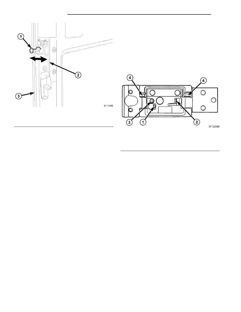
(11) Check and adjust the hinges. On rear doors,

the retaining magnets should run up to the middle of
the mating plate at the side wall. If this is not the
case, correct as listed. (Fig. 11)

CAUTION: Adjustment range of screw (3) maximum
1 turn (risk of control cam breaking, 4)

• Retaining magnet is too far forward relative to

mating plate. Turn in adjustment screw (2) at top
and bottom hinge.

• Retaining magnet is too far back relative to mat-

ing plate. Turn out adjustment screw (2) at top and
bottom hinge.

• Retaining magnet is too deep relative to mating

plate. Turn in adjustment screw (2) at top hinge,
turn out adjustment screw (2) at bottom hinge.

• Retaining magnet is too high relative to mating

plate. Turn out adjustment screw (2) at top hinge,
turn in adjustment screw (2) at bottom hinge.

• Retaining magnet strikes too hard against mat-

ing plate. Turn in adjustment screw (1) at top and
bottom hinge.

• Retaining magnet does not make contact with

mating plate. Turn out adjustment screw (1) at top
and bottom hinge.

• Door projects at corner paneling when closed.

Turn out adjustment screw (3) at hinge.

• Door is too far recessed at corner paneling when

closed. Turn in adjustment screw (3) at hinge.

DOOR GLASS

REMOVAL

(1) Position an assistant on one side of the door to

receive the glass and weatherstrip seal.

(2) Start at an inside, upper corner. Separate the

seal from the window opening. Push the glass and
seal outward from the window opening. Remove the
glass and seal.

(3) Clean the window opening.

INSTALLATION

(1) Install the weatherstrip seal on the window

glass. Verify that the glass is seated in the groove
around the edge of the seal.

(2) Insert an installation cord in the weatherstrip

seal inner groove.

NOTE: Use mineral spirits as a lubricant to aid seal
installation in the window opening.

(3) Position the glass and seal in the window open-

ing.

(4) Pull the installation cord outward and force the

seal lip over the panel flange around the edge of the
opening.

(5) Seat the seal inner lip on the panel flange.

Press against the lip around the edge of the seal.

Fig. 10 STRIKER ADJUSTMENT

1 - STRIKER
2 - LOCK ROD HANDLE ASSEMBLY
3 - LEFT DOOR

Fig. 11 REAR HINGE ADJUSTMENT

1 - ADJUSTMENT SCREW
2 - ADJUSTMENT SCREW
3 - ADJUSTMENT SCREW
4 - CONTROL ARM

23 - 30

DOORS - REAR

VA

NOTE: Remove any mineral spirits with a clean
cloth after glass installation.

(6) Verify that the seal is seated in the window

opening (Fig. 12).

(7) Test the window for water leaks. (Refer to 23 -

BODY - DIAGNOSIS AND TESTING - WATER
LEAKS)

EXTERIOR HANDLE

REMOVAL

(1) Remove handle bolt. (Fig. 13)

NOTE: Front door shown, rear door similar.

(2) Slide handle assembly towards front of door.

(Fig. 14)

NOTE: Front door shown, rear door similar.

(3) Pull rear of handle out away from door and dis-

engage the latch levers.

(4) Slide handle towards the rear of door and

remove.

INSTALLATION

(1) Position front of handle into front slot in door.

(Fig. 15)

NOTE: Front door shown, rear door similar.

Fig. 12 Glass & Weatherstrip Seal Installation

1 - BODY PANEL
2 - WEATHERSTRIP SEAL
3 - INSTALLATION CORD
4 - WINDOW OPENING

Fig. 13 EXTERIOR HANDLE

1 - EXTERIOR HANDLE BOLT
2 - LATCH
3 - LATCH BOLTS (3)

Fig. 14 LATCH/HANDLE FASTENERS

1 - EXTERIOR HANDLE
2 - DOOR

VA

DOORS - REAR

23 - 31

(2) Position rear of handle into latch opening and

engage lock and latch actuation levers with the latch
levers. (Fig. 16)

NOTE: Front door shown, rear door similar.

(3) Slide exterior handle towards rear of door and

install bolt. (Fig. 17)

NOTE: Front door shown, rear door similar.

(4) Tighten bolt to 10 N·m (89 in. lbs.).

HINGE

REMOVAL

NOTE: It is not necessary to remove the door to
replace the hinges if they are replaced one at a
time.

(1) Using a grease pencil or equivalent, mark the

position of the hinge on the door.

(2) Remove the bolts and remove the hinge. (Fig.

18)

Fig. 15 EXTERIOR HANDLE INSTALLATION

1 - DOOR LATCH OPENING
2 - LOCK ACTUATION LEVER
3 - LATCH ACTUATION LEVER
4 - EXTERIOR HANDLE

Fig. 16 LATCH LEVERS

1 - LATCH LEVER
2 - LATCH OPENING
3 - LOCK LEVER

Fig. 17 EXTERIOR HANDLE

1 - EXTERIOR HANDLE BOLT
2 - LATCH
3 - LATCH BOLTS (3)

23 - 32

DOORS - REAR

VA

INSTALLATION

(1) Install hinge and install bolts.
(2) Tighten bolts to 25 N·m (18 ft. lbs.).
(3) Adjust door if necessary. (Refer to 23 - BODY/

DOOR - FRONT/DOOR - ADJUSTMENTS)

INSIDE HANDLE ACTUATOR

REMOVAL

(1) Remove the handle trim cover. (Fig. 19)
(2) Remove the screws and handle.
(3) Disconnect the latch cable.

INSTALLATION

(1) Connect the latch cable.
(2) Install handle and screws.
(3) Install trim cover.

LATCH

REMOVAL

(1) Disconnect and isolate battery negative cable.
(2) Remove right side trim panel. (Refer to 23 -

BODY/DOORS - REAR/TRIM PANEL - REMOVAL)

(3) Disconnect lock rod. (Fig. 20)
(4) Remove the screws and pull out latch from

door.

(5) Disconnect cable and electrical connectors.

Fig. 18 REAR DOOR HINGE

1 - TORX BOLTS BODY SIDE
2 - TORX BOLTS DOOR SIDE
3 - HINGE
4 - ALLEN BOLT

Fig. 19 TRIM PANEL

1 - TRIM
2 - INSIDE HANDLE ACTUATOR
3 - TRIM PANEL
4 - CONTROL CABLE

VA

DOORS - REAR

23 - 33


Content   ..  313  314  315  316   ..