Dodge Sprinter. Manual - part 314
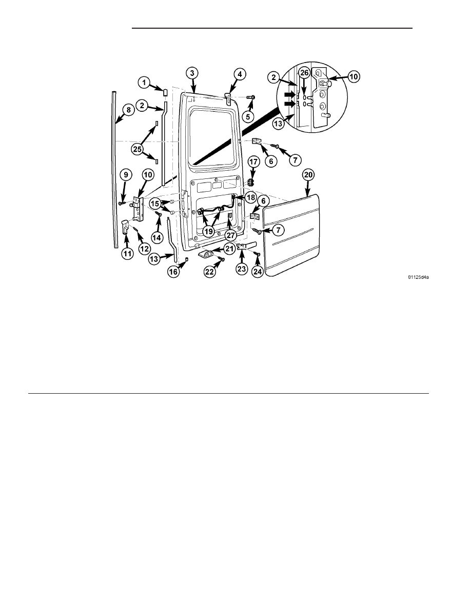
LEFT DOOR
(1) Remove door. (Refer to 23 - BODY/DOORS -
REAR/DOOR - REMOVAL)
(2) Remove trim panel (20) (Fig. 5). (Refer to 23 -
BODY/DOORS - REAR/TRIM PANEL - REMOVAL)
(3) Disconnect electrical connectors and remove
license plate lighting (18, 19).
(4) Pull out switch and disconnect electrical con-
nector (17).
(5) Remove and discard roll pin (12) and remove
lock rod handle (11).
(6) Remove door check (23). (Refer to 23 - BODY/
DOORS - REAR/CHECK - REMOVAL)
(7) Remove door hinge (6). (Refer to 23 - BODY/
DOORS - REAR/HINGE - REMOVAL)
(8) Remove closing wedge (4).
(9) Remove rivets (22) and remove bottom closing
wedge (21).
(10) Remove rear door seal (8).
(11) Remove the four screws (9, 14) from the lock
rod actuator.
(12) Using locking pliers, hold upper lock rod (2)
and remove lock rod actuator.
(13) Remove clips (15).
(14) Pull out lock rod guides (1, 16) and remove
lock rods (2, 13).
Fig. 5 LEFT DOOR
1 - UPPER LOCK ROD GUIDE
15 - CLIPS (2)
2 - UPPER LOCK ROD
16 - BOTTOM LOCK ROD GUIDE
3 - LEFT REAR DOOR
17 - SWITCHES
4 - TOP CLOSING WEDGE
18 - ELECTRICAL CONNECTOR
5 - BOLTS (2)
19 - LICENSE PLATE LIGHTING
6 - HINGE
20 - TRIM PANEL
7 - BOLTS (2)
21 - BOTTOM CLOSING WEDGE
8 - REAR DOOR SEAL
22 - RIVETS (2)
9 - SCREWS (2)
23 - DOOR CHECK
10 - LOCK ROD ACTUATOR
24 - BOLTS (2)
11 - LOCK ROD HANDLE
25 - FELT STRIP
12 - ROLL PIN
26 - O-RINGS (2)
13 - BOTTOM LOCK ROD
27 - THREADED PLATE
14 - SCREWS (2)
23 - 26
DOORS - REAR
VA