Dodge Neon / Neon SRT-4. Manual - part 594
TEST
ACTION
APPLICABILITY
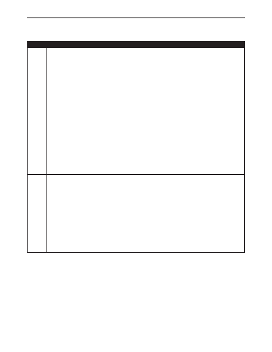
6
Turn the ignition off.
Disconnect the hoses from the TIP Solenoid.
Install a plug on the TIP Solenoid hose B connection point.
Connect a vacuum pump to the TIP Solenoid hose A connection point.
With vacuum pump apply 20 inches of vacuum to the TIP Solenoid hose A connection
point.
NOTE: Vacuum reading should not drop below 10 inches within 5 seconds.
Does vacuum read above 10 inches for at least 5 seconds?
All
Yes
→ Go To 7
No
→ Replace the TIP Solenoid.
Perform POWERTRAIN VERIFICATION TEST VER - 5.
7
Turn the ignition off.
Disconnect the hoses from the TIP Solenoid.
Install a plug on the TIP Solenoid hose C connection point.
Connect a vacuum pump to the TIP Solenoid hose A connection point.
Attempt to apply 20 inches of vacuum to the TIP Solenoid hose A connection point.
NOTE: Vacuum should escape through the Solenoid hose B connection
point.
Does vacuum escape through the Solenoid hose B connection point?
All
Yes
→ Go To 8
No
→ Replace the TIP Solenoid.
Perform POWERTRAIN VERIFICATION TEST VER - 5.
8
Turn the ignition off.
Disconnect the hoses from the TIP Solenoid.
Install a plug on TIP Solenoid hose C connection point.
Connect a vacuum pump to the TIP Solenoid hose B connection point.
NOTE: For the result of this test to be accurate the solenoid must be turned
on. Apply 12 volts and Ground to the appropriate solenoid terminals to turn
the solenoid on.
With vacuum pump apply 20 inches of vacuum to the TIP Solenoid hose B connection
point.
NOTE: Vacuum reading should not drop below 10 inches within 5 seconds.
Does vacuum read above 10 inches for at least 5 seconds?
All
Yes
→ Go To 9
No
→ Replace the TIP Solenoid.
Perform POWERTRAIN VERIFICATION TEST VER - 5.
281
DRIVEABILITY - NGC
P1854-TIP BARO OUT OF RANGE —
Continued