Index Dodge Dodge Neon / Neon SRT-4 - service repair manual 2005 year
Search
Content .. 524 525 526 527 ..
Dodge Neon / Neon SRT-4. Manual - part 526
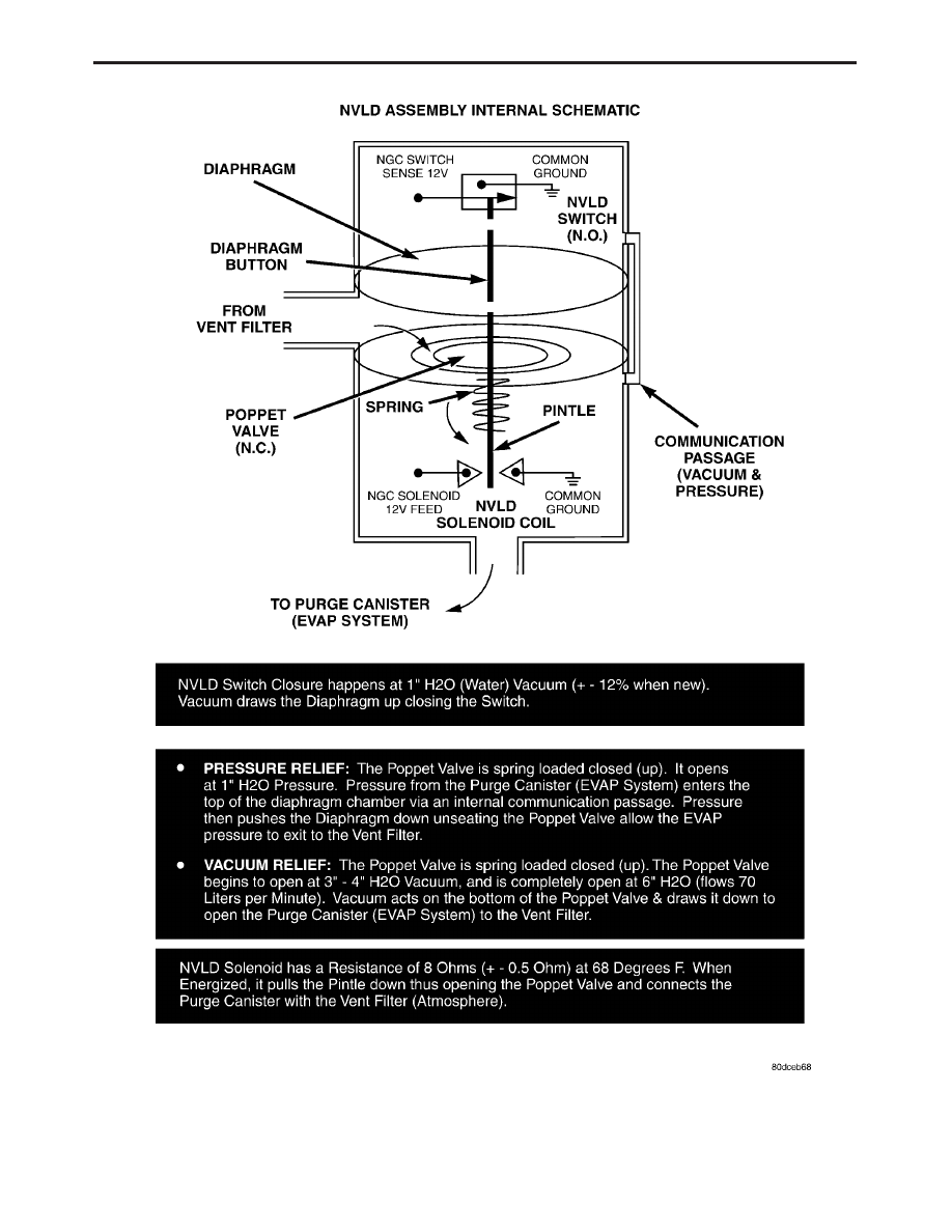
FIGURE 2
9
GENERAL INFORMATION