Dodge Neon / Neon SRT-4. Manual - part 521
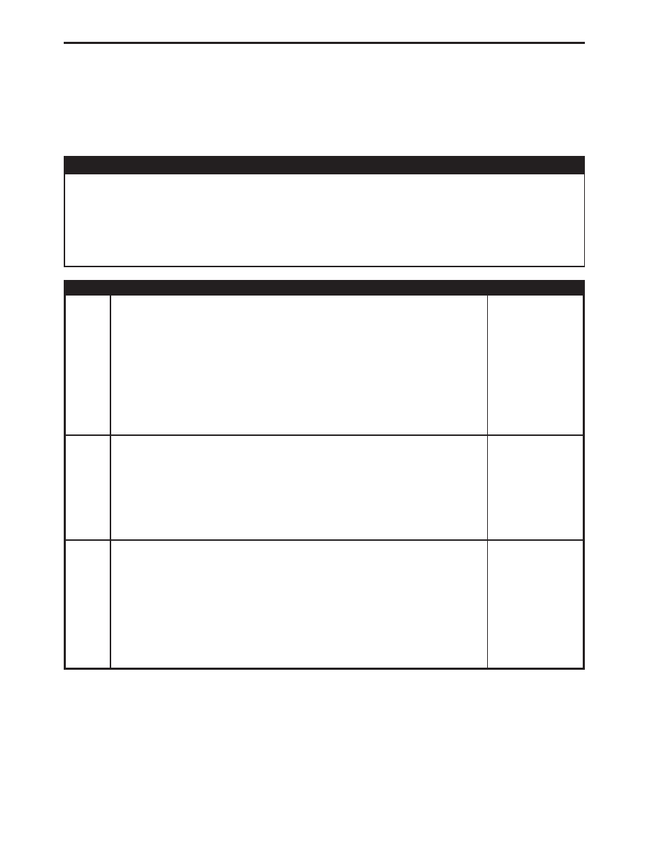
Symptom:
*NO RESPONSE FROM CONTROLLER ANTILOCK BRAKE
POSSIBLE CAUSES
NO RESPONSE FROM CAB
GROUND CIRCUIT OPEN
OPEN FUSED IGNITION SWITCH OUTPUT CIRCUIT
OPEN PCI BUS CIRCUIT
CONTROLLER ANTILOCK BRAKE
TEST
ACTION
APPLICABILITY
1
Turn the ignition on.
Note: As soon as one or more module communicates with the DRB, answer
the question.
With the DRB, attempt to communicate with the Airbag Control Module (ACM).
With the DRB, attempt to communicate with the Instrument Cluster (MIC).
Was the DRB able to I/D or establish communications with either of the modules?
All
Yes
→ Go To 2
No
→ Refer to the Communications category and perform the symptom
PCI Bus Communication Failure.
Perform ABS VERIFICATION TEST - VER 1.
2
Turn the ignition off.
Disconnect the CAB harness connector.
Using a 12-volt test light connected to 12-volts, probe both ground circuits.
Is the test light illuminated for both circuits?
All
Yes
→ Go To 3
No
→ Repair the ground circuit(s) for an open.
Perform ABS VERIFICATION TEST - VER 1.
3
Turn the ignition off.
Disconnect the CAB harness connector.
Turn the ignition on.
Using a 12-volt test light connected to ground, probe the Fused Ignition Switch
Output circuit.
Is the test light illuminated?
All
Yes
→ Go To 4
No
→ Repair the Fused Ignition Switch Output circuit for an open.
Perform ABS VERIFICATION TEST - VER 1.
36
COMMUNICATION