Dodge Neon / Neon SRT-4. Manual - part 520
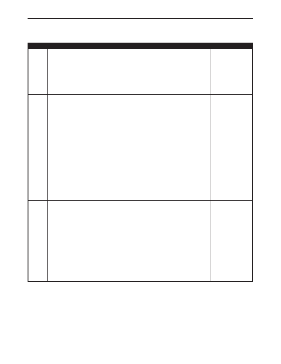
TEST
ACTION
APPLICABILITY
3
Turn the ignition off.
Disconnect the CAB harness connector.
Inspect the CAB and CAB harness connector for damage.
Is there any broken, bent, pushed out, corroded, or spread terminals?
All
Yes
→ Repair as necessary.
Perform ABS VERIFICATION TEST - VER 1.
No
→ Go To 4
4
Turn the ignition off.
Disconnect the CAB harness connector.
Using a 12-volt test light connected to 12-volts, probe the Ground circuits.
Does the test light illuminate?
All
Yes
→ Go To 5
No
→ Repair the Ground circuit for an open.
Perform ABS VERIFICATION TEST - VER 1.
5
Turn the ignition on.
Using a 12-volt test light connected to ground, probe the Fused Ignition Switch
Output (RUN) circuit.
Does the test light illuminate?
All
Yes
→ Replace the Controller Antilock Brake in accordance with the
Service Information.
Perform ABS VERIFICATION TEST - VER 1.
No
→ Repair the Fused Ignition Switch Output (RUN) circuit for an
open.
Perform ABS VERIFICATION TEST - VER 1.
6
Turn the ignition off.
Visually inspect the related wiring harness. Look for any chafed, pierced, pinched, or
partially broken wires.
Visually inspect the related wire harness connectors. Look for broken, bent, pushed
out, or corroded terminals.
Refer to any Hotline letters or Technical Service Bulletins that may apply.
Ensure the battery is fully charged.
Inspect the vehicle for aftermarket accessories that may exceed the Generator
System output.
Using the wiring diagram/schematic as a guide, inspect the wiring and connectors.
Were any problems found?
All
Yes
→ Repair as necessary.
Perform ABS VERIFICATION TEST - VER 1.
No
→ Test Complete.
32
BRAKES (CAB)
SYSTEM UNDER VOLTAGE —
Continued