Dodge Neon / Neon SRT-4. Manual - part 394


  Index      Dodge     Dodge Neon / Neon SRT-4 - service repair manual 2005 year


Search            


Content   ..  392  393  394  395   ..


Dodge Neon / Neon SRT-4. Manual - part 394


(4) Install the (4) instrument panel retaining bolts

to the right and left side body side cowls.

(5) Install the (2) instrument panel retaining bolts

which attach the instrument panel to the body at the
tunnel bracket.

(6) Install the (4) instrument panel retaining fas-

teners to the top of the instrument panel.

(7) Connect the radio antenna located below the

glove compartment.

(8) Connect the left door wire harness connector.
(9) Connect the right door wire harness connector.
(10) Connect the ACM, parking brake, and trans-

mission range indicator lamp wiring connectors if
equipped.

(11) Connect the (3) wire harnesses to the top of

the instrument panel.

(12) Connect the instrument panel wire harness

connector. Install the plastic clips to the connector
retainer. To connect the harness install the (2) screws
retaining the instrument panel connector to the
steering column casting. Connect the instrument
panel wire harness to the right kick panel.

(13) Clip the Data Link Connector (DLC) to the

right side of the instrument panel reinforcement.

(14) Pull the control through the instrument panel

and rotate the control horizontally to position the
assembly through the hole in the instrument panel.
Install the (2) HVAC control head retaining screws.

(15) Install the center bezel. Gently push it to

snap the (4) retaining clips.

(16) Install the (2) screws to the center instrument

bezel.

(17) Install the (4) HVAC control knobs by pushing

them straight on the switch shaft by hand.

(18) Position the A/C outlets over the outlet hous-

ing and firmly snap into place. Verify that they pivot
properly.

(19) Install the right and left side lower kick pan-

els and replace the weather-stripping if removed.

(20) Install the steering column into the vehicle.

Install the (4) steering column retaining nuts.

(21) Connect the upper and lower steering column

shafts. Install the steering shaft coupler pinch bolt.

(22) Install the steering shaft coupler pinch bolt

retaining pin.

(23) Connect the clockspring, wiper/washer, multi-

function, ignition and if equipped, the two SKIM
module connections and the shift interlock cable on
automatic transaxle equipped vehicles.

(24) Install the (2) screws retaining the steering

column shroud and install the shroud on the steering
column.

(25) Install the (2) screws retaining the lower

steering column cover.

(26) Install the instrument cluster bezel. Refer to

Body,

Instrument

Panel,

Instrument

Panel

Top

Cover, Installation.

(27) Install the instrument panel top cover.
(28) Install the (2) screws retaining the instrument

panel top cover. Located in the defroster grille.

(29) Install the right and left side A-pillar trims.

Refer to Body, Interior.

(30) Install the right and left side instrument

panel end cover.

(31) Install the floor console. Refer to Body, Inte-

rior, Center Console, Installation.

(32) Disconnect the battery negative cable.

INSTRUMENT PANEL CENTER
BEZEL

REMOVAL

(1) Remove HVAC control knobs from control head.
(2) Remove both center A/C outlet louvers (Fig. 15)

by rolling downward and pulling out.

(3) Remove two screws retaining the top front of

the center bezel up inside the center A/C outlet duct.

(4) Using a trim stick (special tool #C-4755) or

equivalent, gently pry out on instrument panel cen-
ter bezel.

(5) Remove bezel from vehicle.

INSTALLATION

(1) Position the instrument panel center bezel over

mounting slots and firmly snap into place.

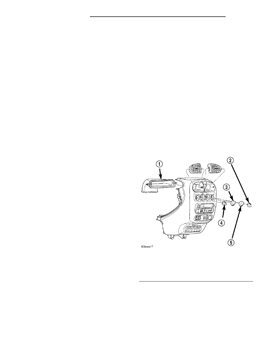
Fig. 15 A/C OUTLET LOUVERS

1 - INSTRUMENT PANEL CENTER AIR DUCT
2 - OUTSIDE AIR/RECIRC CONTROL KNOB
3 - MODE CONTROL KNOB
4 - BLOWER SPEED KNOB
5 - TEMPERATURE CONTROL KNOB

23 - 60

INSTRUMENT PANEL

PL/SRT-4

INSTRUMENT PANEL ASSEMBLY (Continued)

(2) Install the two screws retaining the top front of

the center bezel up inside the center A/C outlet duct.

(3) Install both center A/C outlet louvers (Fig. 15)

by snapping into place.

(4) Install the HVAC control knobs onto the control

head.

INSTRUMENT PANEL END
COVER

REMOVAL

(1) The driver’s end cover can be removed using

the handle. Using a trim stick (special tool #C-4755)
or equivalent, gently pry out on the right end cover
and remove. The fuse diagram is located inside the
left end cover. Fuse Access is under the left end
cover.

INSTALLATION

(1) Guide the end cover under the forward lip of

the door seal and position the end cover over the
mounting slots and firmly snap into place.

(2) Close door.

STORAGE BIN

REMOVAL

(1) Using a trim stick (special tool #C-4755) or

equivalent, gently pry out on the side of the lower
storage bin.

(2) Disconnect the center console flood lamp.
(3) Transfer the center console flood lamp housing

to new bin (if replacing).

INSTALLATION

(1) Transfer the center console flood lamp housing

to new bin (if replacing).

(2) Connect the center console flood lamp.
(3) Position the storage bin over mounting slots

and firmly snap into place.

INSTRUMENT PANEL TOP
COVER

REMOVAL

(1) Loosen the two screws at each end off the

defroster slot until they are flush with top cover sur-
face (DO NOT REMOVE).

(2) Remove the screw at each end of the top cover.
(3) Using a trim stick (special tool #C-4755) or

equivalent, gently pry out on both the left and right
A-pillar trim panels and remove.

(4) Use care not to scratch the panel. Lift up at

each end of the cluster bezel and along the rearward
edge of the top cover to disengage the clips.

(5) Pull the top cover rearward until the forward

pins disengage from the instrument panel.

INSTALLATION

(1) Push the top cover forward assuring that the

pins on the top cover engage the slots in the in the
instrument panel.

(2) Use care not to scratch the panel. Position the

top cover clips over their mounting slots and start
the retaining clips into each slot. Starting in the mid-
dle, firmly snap the top cover into place using a firm
blow with the hand at each clip position.

(3) Align the left and right A-pillar trim panels

over the mounting slots and firmly snap into place.

STEERING COLUMN OPENING
COVER

REMOVAL

(1) Remove instrument cluster bezel. (Refer to 23 -

BODY/INSTRUMENT PANEL/CLUSTER BEZEL -
REMOVAL)

(2) Remove the two screws along the lower edge of

the cover.

(3) Grasp left lower steering column cover from

the bottom and pull rearward to disengage clips.

(4) Remove steering column cover from vehicle.

INSTALLATION

(1) Position the left lower steering column cover

over mounting slots and firmly snap into place.

(2) Install the two lower cover retaining screws.
(3) Install the instrument cluster bezel. (Refer to

23

-

BODY/INSTRUMENT

PANEL/CLUSTER

BEZEL - INSTALLATION)

PL/SRT-4

INSTRUMENT PANEL

23 - 61

INSTRUMENT PANEL CENTER BEZEL (Continued)

INTERIOR

TABLE OF CONTENTS

page

page

A-PILLAR TRIM

REMOVAL

. . . . . . . . . . . . . . . . . . . . . . . . . . . . . 62

INSTALLATION

. . . . . . . . . . . . . . . . . . . . . . . . . 62

B-PILLAR TRIM

REMOVAL

. . . . . . . . . . . . . . . . . . . . . . . . . . . . . 62

INSTALLATION

. . . . . . . . . . . . . . . . . . . . . . . . . 62

CARPETS AND FLOOR MATS

REMOVAL

. . . . . . . . . . . . . . . . . . . . . . . . . . . . . 63

INSTALLATION

. . . . . . . . . . . . . . . . . . . . . . . . . 63

DOOR SILL TRIM

REMOVAL

. . . . . . . . . . . . . . . . . . . . . . . . . . . . . 64

INSTALLATION

. . . . . . . . . . . . . . . . . . . . . . . . . 64

FLOOR CONSOLE

REMOVAL

. . . . . . . . . . . . . . . . . . . . . . . . . . . . . 64

INSTALLATION

. . . . . . . . . . . . . . . . . . . . . . . . . 65

HEADLINER

REMOVAL

. . . . . . . . . . . . . . . . . . . . . . . . . . . . . 65

INSTALLATION

. . . . . . . . . . . . . . . . . . . . . . . . . 65

LOWER QUARTER TRIM

REMOVAL

. . . . . . . . . . . . . . . . . . . . . . . . . . . . . 65

INSTALLATION

. . . . . . . . . . . . . . . . . . . . . . . . . 65

REAR SHELF TRIM PANEL

REMOVAL

. . . . . . . . . . . . . . . . . . . . . . . . . . . . . 66

INSTALLATION

. . . . . . . . . . . . . . . . . . . . . . . . . 66

REAR VIEW MIRROR

REMOVAL

. . . . . . . . . . . . . . . . . . . . . . . . . . . . . 66

INSTALLATION

. . . . . . . . . . . . . . . . . . . . . . . . . 66

SIDE COWL TRIM

REMOVAL

. . . . . . . . . . . . . . . . . . . . . . . . . . . . . 66

INSTALLATION

. . . . . . . . . . . . . . . . . . . . . . . . . 66

SUN VISOR

REMOVAL

. . . . . . . . . . . . . . . . . . . . . . . . . . . . . 67

INSTALLATION

. . . . . . . . . . . . . . . . . . . . . . . . . 67

TRUNK LINING

REMOVAL

. . . . . . . . . . . . . . . . . . . . . . . . . . . . . 67

INSTALLATION

. . . . . . . . . . . . . . . . . . . . . . . . . 67

UPPER QUARTER TRIM

REMOVAL

. . . . . . . . . . . . . . . . . . . . . . . . . . . . . 67

INSTALLATION

. . . . . . . . . . . . . . . . . . . . . . . . . 68

A-PILLAR TRIM

REMOVAL

(1) Disengage clips holding trim to A-pillar.
(2) Separate A-pillar trim from vehicle (Fig. 1).

INSTALLATION

(1) Position A–pillar trim panel to A–pillar.

(2) Align locating pins on backside of trim panel to

mating holes in A–pillar.

(3) Push clips on trim panel into slots in A–pillar.

B-PILLAR TRIM

REMOVAL

(1) Remove bolt attaching lower seat belt anchor to

floor pan kick-up (Fig. 2).

(2) Remove shoulder belt height control knob.
(3) Remove turning loop cover.
(4) Remove bolt and remove the turning loop.
(5) Remove bolt attaching turning loop to belt

adjuster (Fig. 3).

(6) Remove access cover from B-pillar trim.
(7) Disengage clips attaching trim to B-pillar.
(8) Feed seat belt turning loop and seat belt

through trim panel.

(9) Remove B-pillar trim from vehicle.

INSTALLATION

NOTE: Tighten all seat belt bolts to 40 N·m (30 ft.
lbs.) torque.

(1) Position B-pillar trim panel near B-pillar.

Fig. 1 A-pillar Trim

1 - WINDSHIELD A-PILLAR
2 - CLIPS
3 - A-PILLAR TRIM

23 - 62

INTERIOR

PL/SRT-4

(2) Feed seat belt turning loop and seat belt

through trim panel.

(3) Align locating pins on backside of trim panel to

mating holes in B-pillar.

(4) Push clips on trim panel into slots in B-pillar.
(5) Install access cover to B-pillar trim.
(6) Install bolt attaching turning loop to belt

adjuster.

(7) Install the turning loop cover.
(8) Move adjuster in to the lowest position.
(9) Install shoulder belt height control knob.
(10) Install bolt attaching lower seat belt anchor to

floor pan kick-up.

CARPETS AND FLOOR MATS

REMOVAL

For removal of the carpet, the carpet will need to

be cut under the instrument panel.

(1) Remove front seats.
(2) Remove rear seat cushion.
(3) Remove bolts attaching front seat belt lower

anchors to floor (Fig. 4).

(4) Remove door sill trim covers.
(5) Remove cowl trim covers.
(6) Remove center floor console.
(7) Remove decklid release assist handle.
(8) Remove lower fasteners from B-pillar trim

panel.

(9) Pull carpet from behind trim panel.
(10) Fold carpet in half toward rear seat.
(11) Remove carpet through rear door opening.

INSTALLATION

The new carpet must be cut for installation. The

area is mark on the reverse side of the carpet. The
location is in front of the tunnel area.

(1) Install carpet through rear door opening.
(2) Unfold carpet.
(3) Tuck carpet behind trim panel.
(4) Install lower fasteners holding B-pillar trim

panel.

(5) Install decklid release assist handle.
(6) Install center floor console.
(7) Install cowl trim covers.
(8) Install door sill trim covers.
(9) Install bolts attaching front seat belt lower

anchors to floor. Tighten all seat belts to 40 N·m (30
ft. lbs.) torque.

(10) Install rear seat cushion.
(11) Install front seats.

Fig. 2 B-pillar Trim

1 - FRONT SEAT BELT ADJUSTER
2 - UPPER B-PILLAR TRIM PANEL
3 - ADJUSTER BUTTON
4 - TURNING LOOP COVER
5 - TURNING LOOP
6 - SEAT BELT
7 - SEAT BELT RETRACTOR
8 - ANCHOR BOLT
9 - LOWER B-PILLAR TRIM PANEL

Fig. 3 Turning Loop to Belt Adjuster

1 - FRONT SHOULDER BELT ADJUSTER
2 - TAB IS ON BOTTOM

PL/SRT-4

INTERIOR

23 - 63

B-PILLAR TRIM (Continued)


Content   ..  392  393  394  395   ..