Dodge Neon / Neon SRT-4. Manual - part 392
INSTRUMENT PANEL
TABLE OF CONTENTS
page
page
CLUSTER BEZEL
. . . . . . . . . . . . . . . . . . . . . . . . . . . . . 52
. . . . . . . . . . . . . . . . . . . . . . . . . 52
ACCESSORY SWITCH BEZEL
. . . . . . . . . . . . . . . . . . . . . . . . . . . . . 52
. . . . . . . . . . . . . . . . . . . . . . . . . 53
GLOVE BOX
. . . . . . . . . . . . . . . . . . . . . . . . . . . . . 53
. . . . . . . . . . . . . . . . . . . . . . . . . 53
INSTRUMENT PANEL ASSEMBLY
. . . . . . . . . . . . . . . . . . . . . . . . . . . 53
. . . . . . . . . . . . . . . . . . . . . . 56
. . . . . . . . . . . . . . . . . . . . . . . 58
. . . . . . . . . . . . . . . . . . 59
INSTRUMENT PANEL CENTER BEZEL
. . . . . . . . . . . . . . . . . . . . . . . . . . . . . 60
. . . . . . . . . . . . . . . . . . . . . . . . . 60
INSTRUMENT PANEL END COVER
. . . . . . . . . . . . . . . . . . . . . . . . . . . . . 61
. . . . . . . . . . . . . . . . . . . . . . . . . 61
STORAGE BIN
. . . . . . . . . . . . . . . . . . . . . . . . . . . . . 61
. . . . . . . . . . . . . . . . . . . . . . . . . 61
INSTRUMENT PANEL TOP COVER
. . . . . . . . . . . . . . . . . . . . . . . . . . . . . 61
. . . . . . . . . . . . . . . . . . . . . . . . . 61
STEERING COLUMN OPENING COVER
. . . . . . . . . . . . . . . . . . . . . . . . . . . . . 61
. . . . . . . . . . . . . . . . . . . . . . . . . 61
CLUSTER BEZEL
REMOVAL
(1) Remove instrument panel top cover. Refer to
Body,
Instrument
Panel,
Instrument
Panel
Top
Cover, Removal.
(2) Using a trim stick (special tool #C-4755) or
equivalent, gently pry up on the cluster bezel and
remove from vehicle.
INSTALLATION
(1) Place the cluster bezel into position and firmly
snap into place.
(2) Install the instrument panel top cover. Refer to
Body,
Instrument
Panel,
Instrument
Panel
Top
Cover, Installation.
ACCESSORY SWITCH BEZEL
REMOVAL
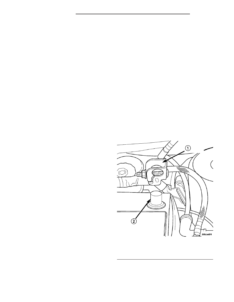
(1) Disconnect and isolate the battery negative
cable (Fig. 1).
(2) Remove the instrument panel center bezel.
Refer to Body, Instrument Panel, Instrument Panel
Center Bezel Removal.
(3) Remove four screws retaining accessory switch
bezel.
(4) Disconnect the harness connectors to the fol-
lowing:
• Rear Window Defogger Switch (if equipped)
• Cigar Lighter/Power Outlet
The accessory switches are not serviced separately,
but the cigar lighter/power outlet is and must be
transferred to the new bezel. Refer to Electrical,
Fig. 1 BATTERY NEGATIVE CABLE REMOVE/
INSTALL
1 - NEGATIVE CABLE
2 - NEGATIVE BATTERY POST
23 - 52
INSTRUMENT PANEL
PL/SRT-4