Dodge Neon / Neon SRT-4. Manual - part 326
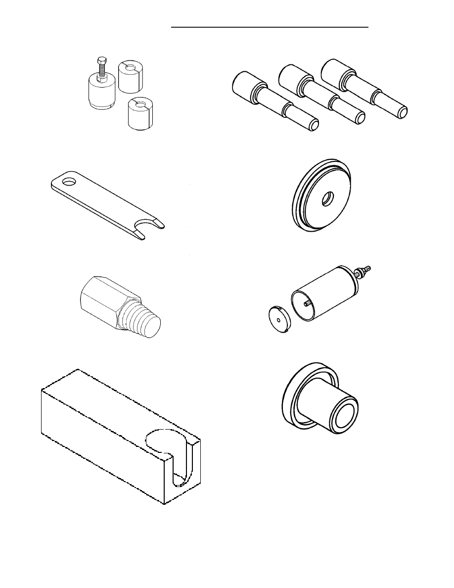
Puller Set, 5048
Disconnect Tool, 6638A
Remover, 6786
Remover/Installer, 6891
Alignment Pins, 8470
Installer, 8471
Race Remover, 8472
Bearing Installer, 8473
21 - 88
T850 MANUAL TRANSAXLE
PL/SRT-4
T850 MANUAL TRANSAXLE (Continued)